
Power supply apparatus for a vehicle

a technology for power supply apparatuses and vehicles, applied in electrical apparatuses, vehicle components, propulsion parts, etc., can solve the problems of complex structure of power supply apparatuses, inability to make small, insufficient cooling, etc., and achieve the effect of simple structur

Inactive Publication Date: 2010-04-22
TOYOTA JIDOSHA KK
View PDF4 Cites 40 Cited by
  • Summary
  • Abstract
  • Description
  • Claims
  • Application Information

AI Technical Summary

Benefits of technology

[0009]This invention thus provides a power supply apparatus which is able to keep a power supply body at an appropriate temperature by means of a. simple structure.
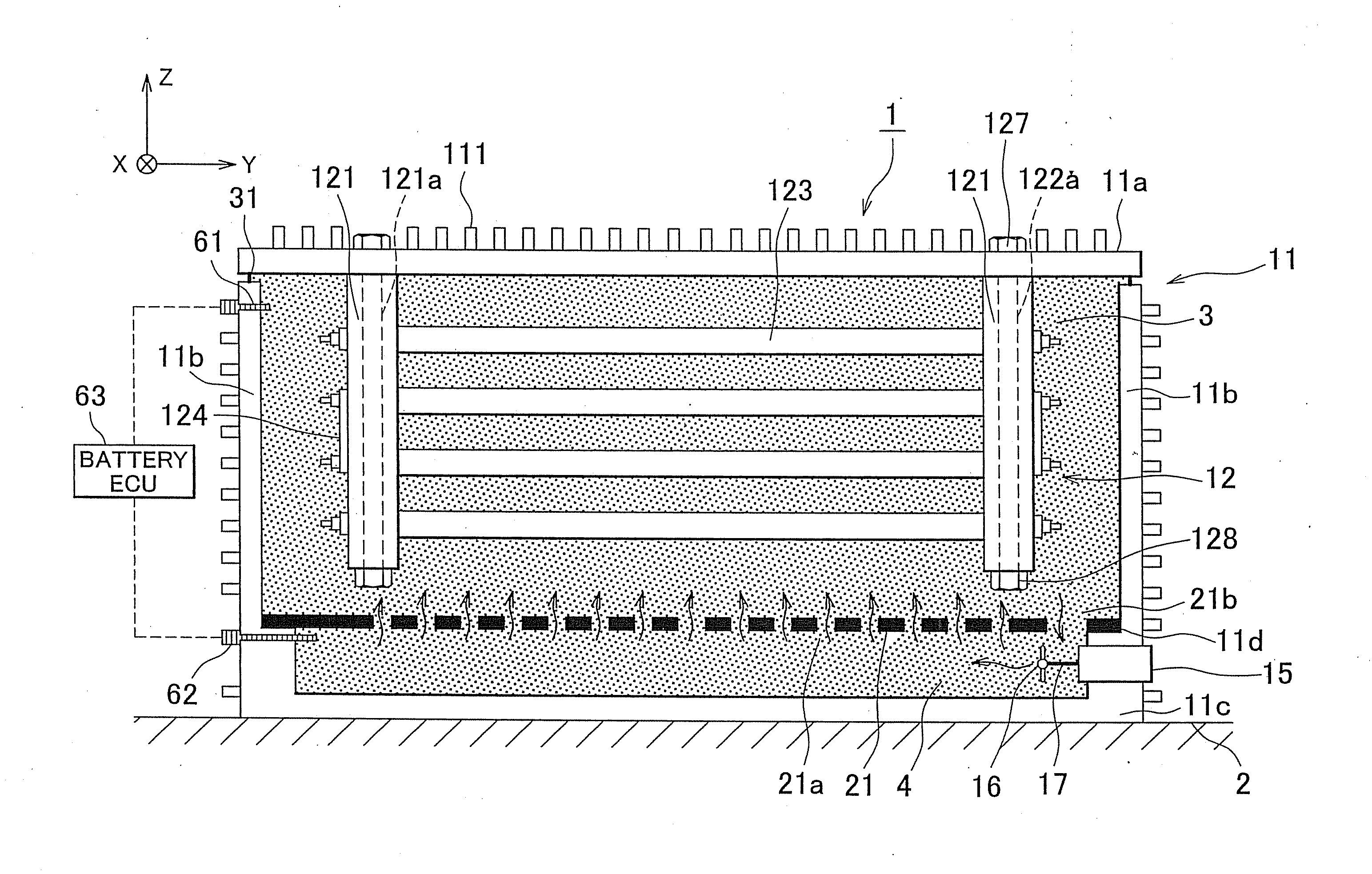
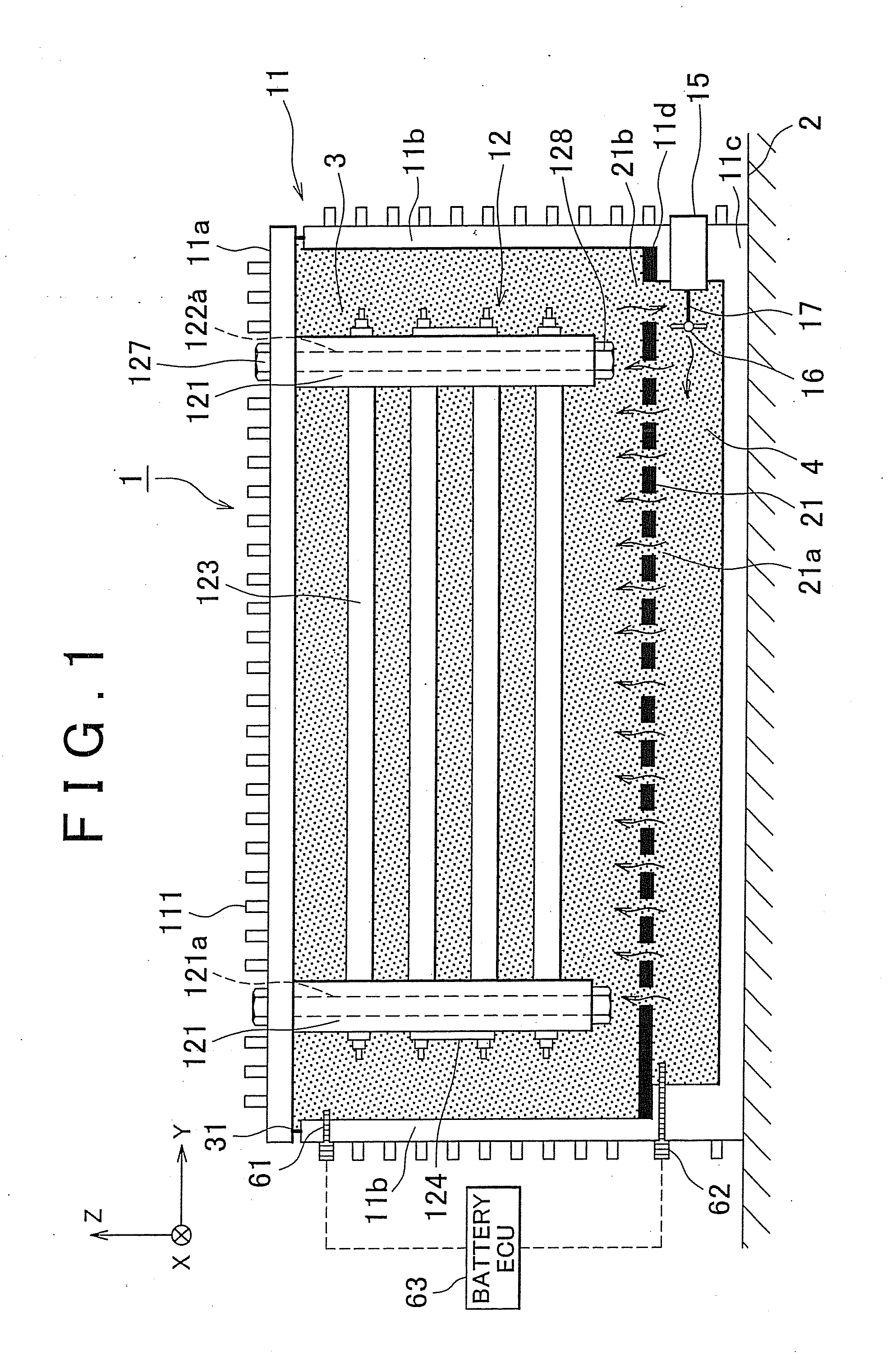
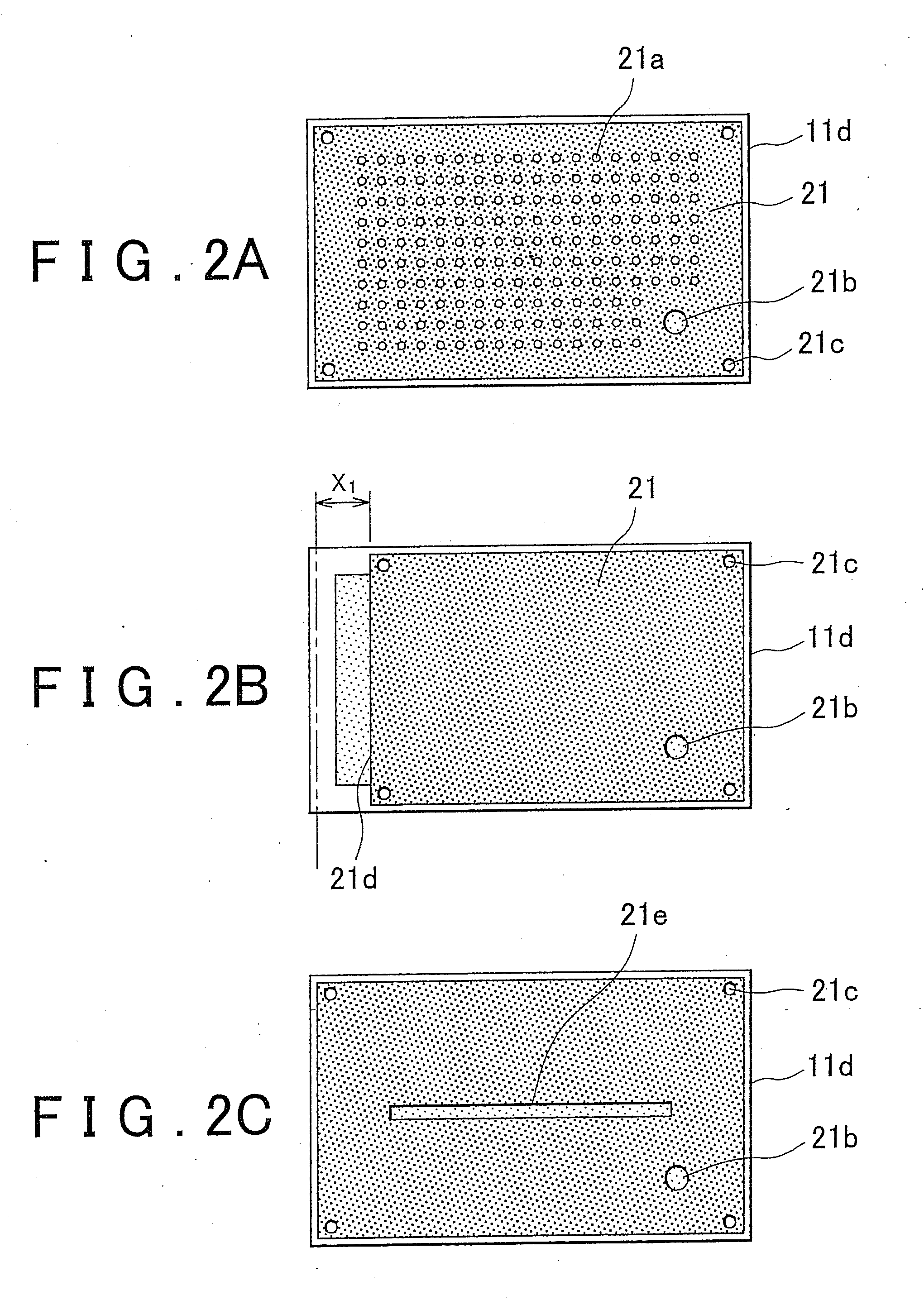
[0021]According to the foregoing aspects and structures, a simple structure in which a dividing plate is arranged inside a power supply case makes it possible to inhibit coolant that is inside the first housing portion from flowing into the second housing portion, thereby inhibiting the heat of the power supply body from being dissipated from the heat transmitting member. Also, when the power supply body needs to be cooled, the coolant inside the first housing portion can be quickly cooled by moving coolant between the first and second housing portions using the circulating means.

Problems solved by technology

As a result, the structure of the power supply apparatus is complicated and unable to be made small.
Also, heat exchange between the assembled battery and the coolant takes place via the inner case so there is a possibility that cooling will be insufficient.
In particular, when the assembled battery is made smaller, the temperature of the heat generated by the assembled battery is higher so cooling via the inner case alone may be insufficient.

Method used


Image

  • Power supply apparatus for a vehicle
  • Power supply apparatus for a vehicle
  • Power supply apparatus for a vehicle

Examples


Embodiment Construction

[0039]Hereinafter, a first example embodiment of the invention will be described.

[0040]First, the general structure of a power supply apparatus 1 will be described with reference to FIG. 1 which is a plan view in the longitudinal direction of the power supply apparatus 1. The power supply apparatus 1 is formed by an assembled battery (power supply body) 12 housed in a battery case 11 that is filled with coolant, and is used as a power supply for driving, or an auxiliary power supply of, an electric vehicle or a hybrid vehicle or the like.

[0041]The assembled battery 12 generates heat at times such as when charging and discharging. If the temperature of that heat becomes excessively high, performance of the battery declines. Therefore, the heat generated by the assembled battery 12 is dissipated outside the vehicle by having the power supply apparatus 1 contacting a floor panel 2 which serves as a heat transmitting member.

[0042]FIG. 9 shows the relationship between battery temperature...


PUM


Abstract

A power supply apparatus in which a power supply body and coolant that cools the power supply body are housed in a power supply case, and in which the power supply case contacts a heat transmitting member, includes a first housing portion that is within the power supply case and houses the power supply body; a second housing portion that is within the power supply case and positioned on the heat transmitting member side of the first housing portion; a dividing plate that allows the coolant to move between the first housing portion and the second housing portion; and circulating means for circulating the coolant between the first housing portion and the second housing portion.

Description

BACKGROUND OF THE INVENTION[0001]1. Field of the Invention[0002]The invention relates to a power supply apparatus that cools a power supply for driving, or an auxiliary power supply of, a hybrid vehicle or an electric vehicle following an exothermic reaction that occurs during charging or discharging of the power supply while driving.[0003]2. Description of the Related Art[0004]Japanese Patent Application Publication No. 2005-19134 (JP-A-2005-19134) describes a power supply apparatus in which an assembled battery is housed in an inner case, and a space for coolant is formed between this inner case and an outer case. The outer case is covered with a battery case protective member which is attached to a portion that is well ventilated such as a floor panel or the overall vehicle body.[0005]A reserve tank that contains coolant is provided outside the outer tank. The reserve tank is connected to the coolant space such that coolant is able to flow between the two. When the assembled batt...

Claims


Application Information

Patent Timeline
IPC IPC(8): H01M10/50H01M10/60B60K1/04H01M10/613H01M10/615H01M10/617H01M10/625H01M10/635H01M10/643H01M10/647H01M10/652H01M10/6551H01M10/6554H01M10/6556H01M10/6568H01M10/658
CPCH01M10/5004H01M10/5016H01M10/5077H01M10/5075H01M10/5046H01M10/613H01M10/625H01M10/6551H01M10/6567H01M10/6568Y02E60/10
Inventor KAWAI, TOSHIYUKI
Owner TOYOTA JIDOSHA KK
Learn More