
Cleaning device, method for detecting suction nozzle clogging, and automatic analyzer

a cleaning device and suction nozzle technology, applied in cleaning equipment, cleaning glassware, instruments, etc., can solve the problems of foreign material in the reaction liquid clogging the nozzle, and achieve the effect of reducing the number of cleaning devices and cleaning equipmen

Inactive Publication Date: 2010-04-22
BECKMAN COULTER INC
View PDF2 Cites 10 Cited by
  • Summary
  • Abstract
  • Description
  • Claims
  • Application Information

AI Technical Summary

Benefits of technology

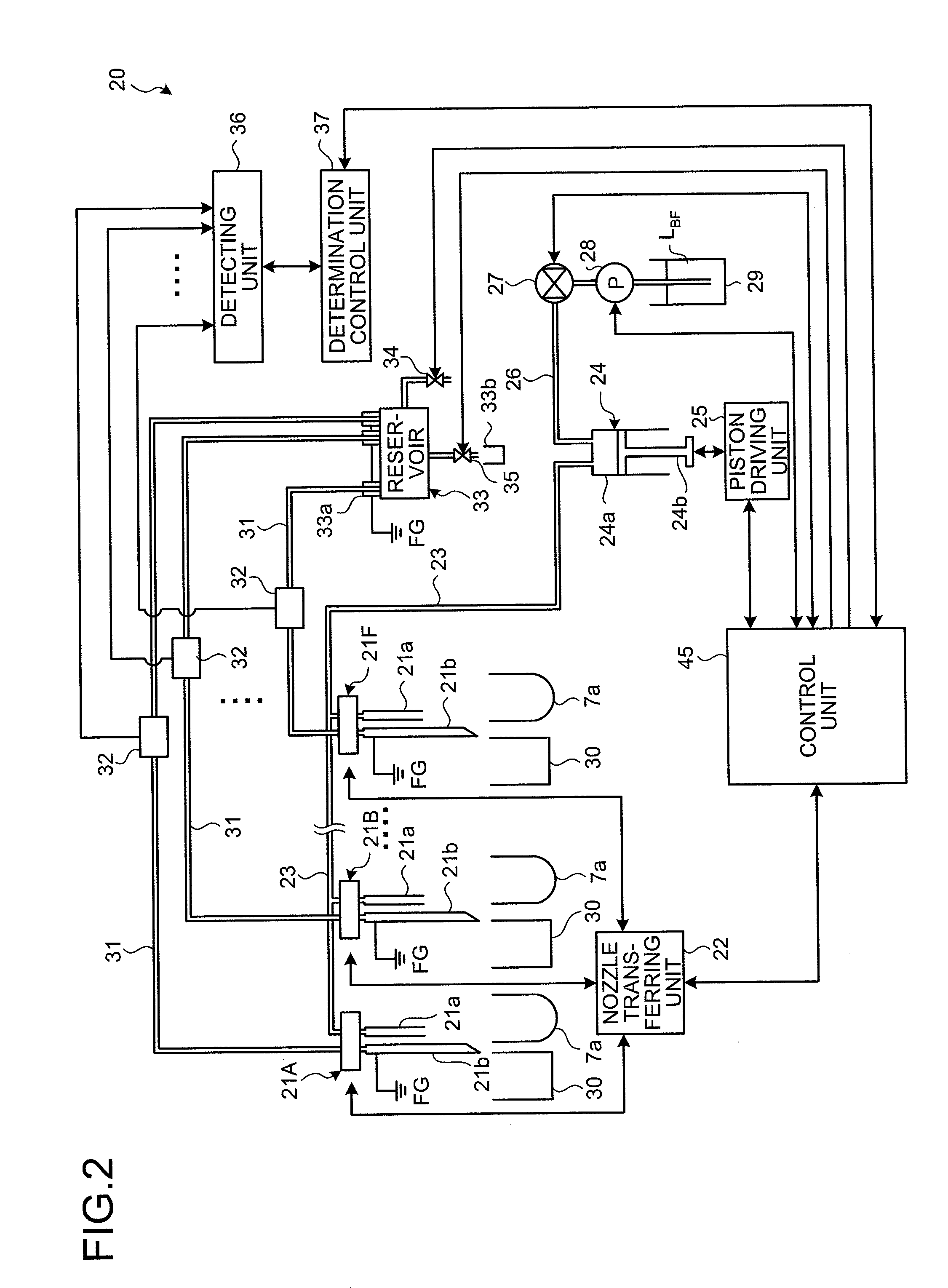
[0007]According to another aspect of the present invention, there is provided a method for detecting suction nozzle clogging in a cleaning device having a discharge nozzle that discharges cleaning liquid, a suction nozzle that is inserted into a cleaning tank or a reaction vessel along with the discharge nozzle to suck cleaning liquid or reaction liquid in the cleaning tank or the reaction vessel, and a discard vessel that is connected to the suction nozzle via a pipe to discard the cleaning liquid or the reaction liquid, the method including detecting whether an electrostatic capacity at least between the suction nozzle and an electrode provided in a middle of the pipe exceeds a predetermined threshold value; and determining that the suction nozzle is clogged when a totalizing time, for which the electrostatic capacity exceeds the predetermined threshold value during a preset clogging determination time, is longer than a totalizing time, for which the electrostatic capacity exceeds the predetermined threshold value during a preset normal determination time.

Problems solved by technology

In such an automatic analyzer, the cleaning device sucks the reaction liquid from the reaction vessel using a nozzle, and sometimes a foreign material in the reaction liquid clogs the nozzle.

Method used


Image

  • Cleaning device, method for detecting suction nozzle clogging, and automatic analyzer
  • Cleaning device, method for detecting suction nozzle clogging, and automatic analyzer
  • Cleaning device, method for detecting suction nozzle clogging, and automatic analyzer

Examples


Embodiment Construction

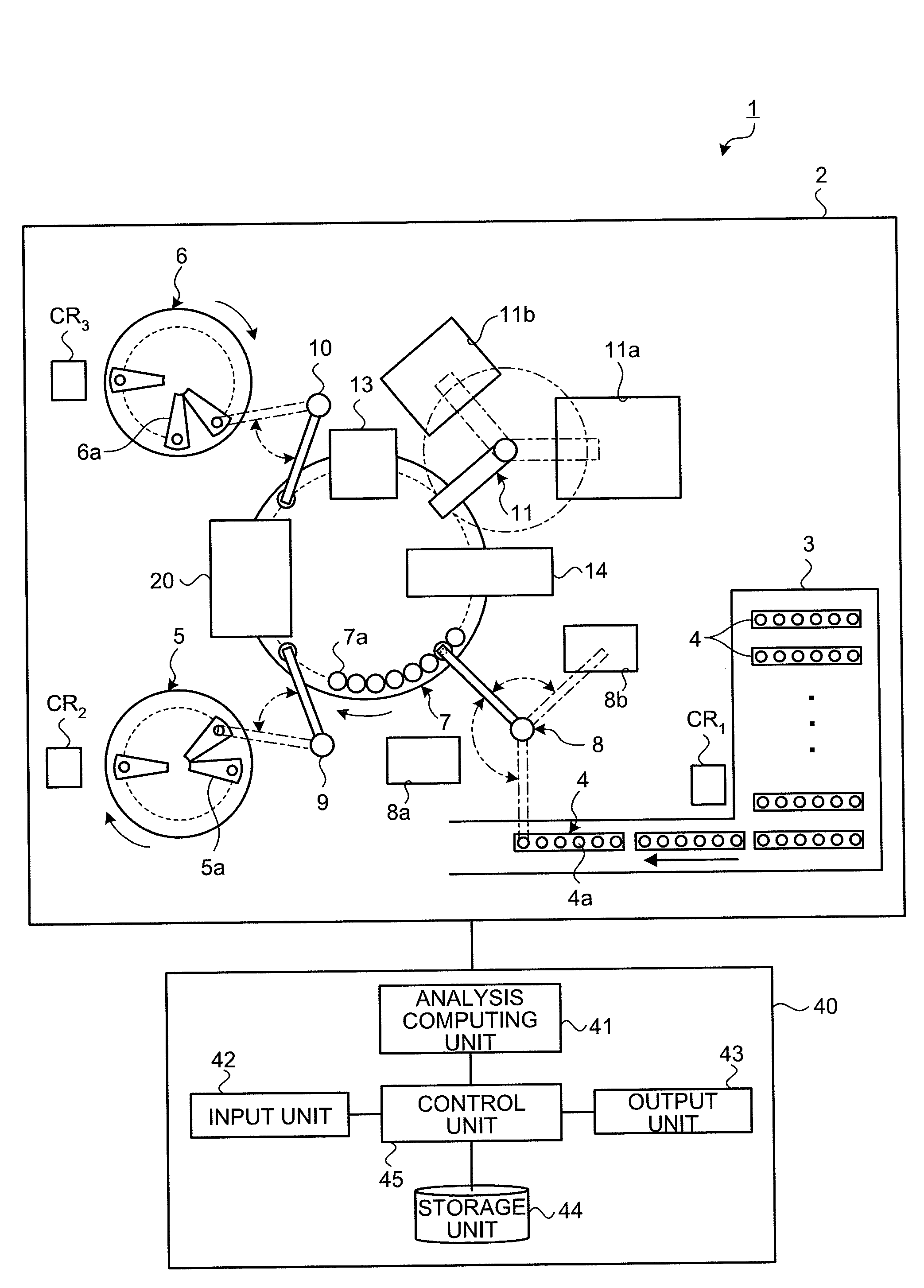
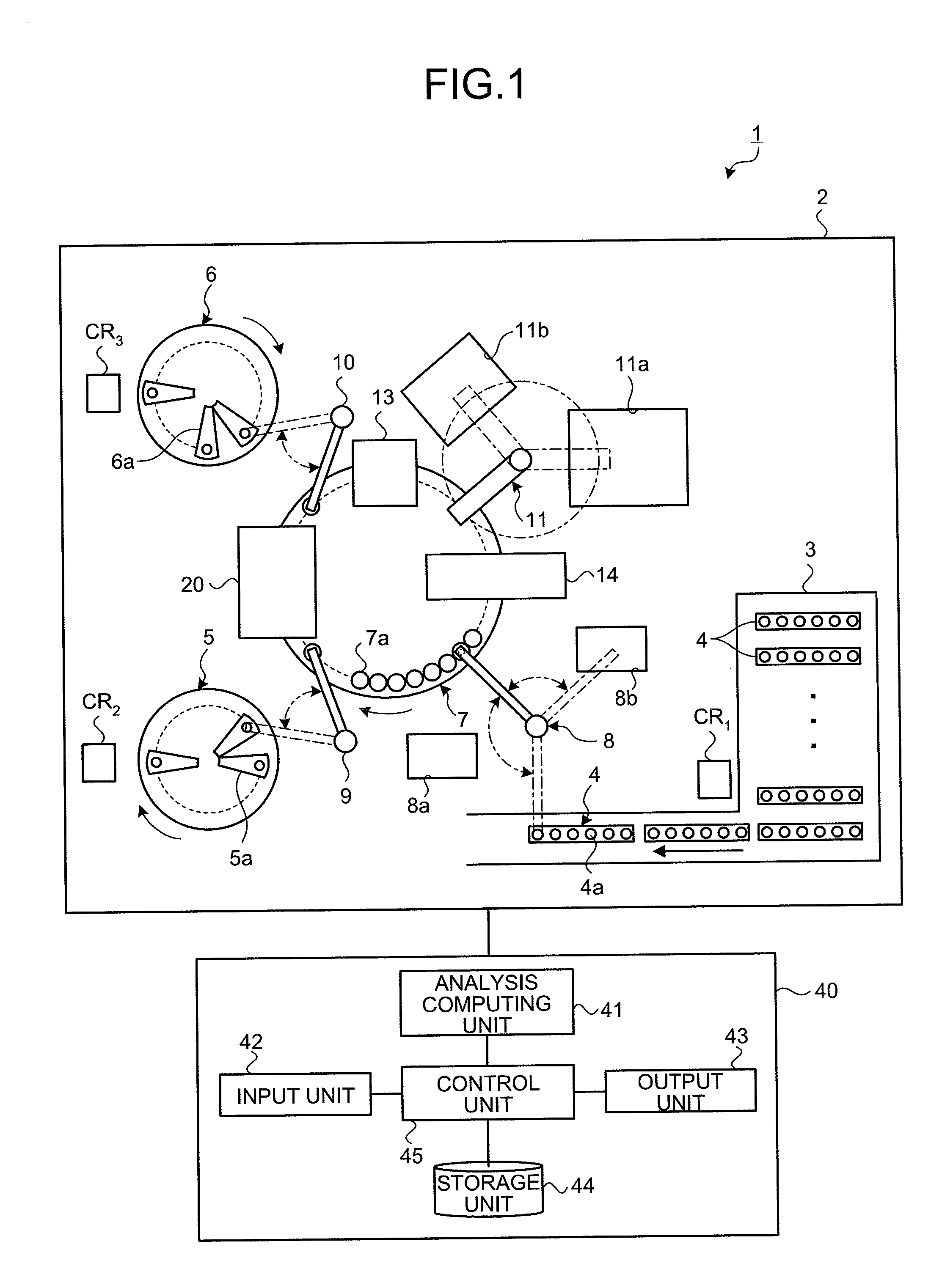
[0025]Exemplary embodiments of a cleaning device, a method for detecting suction nozzle clogging, and an automatic analyzer will be described below in detail with reference to the accompanying drawings. An automatic analyzer for immune analysis, to which the cleaning device and the method for detecting suction nozzle clogging are applied, will be described.

[0026]

[0027]The outline of an immune analysis process performed by an automatic analyzer according to an embodiment of the present invention is described first. In the present embodiment, an immune measurement using a heterogeneous reaction is performed. As an example, a case of measuring the concentration of a predetermined antigen in a specimen using an enzyme immunoassay (EIA) will be explained. In the immune analysis process, an immune reaction (antigen-antibody reaction) is first caused by mixing a specimen and a solid phase that is sensitized by an antibody that specifically couples to a predetermined antigen in the specimen...


PUM


Abstract

A cleaning device includes a discharge nozzle that discharges cleaning liquid; a suction nozzle that sucks the cleaning liquid or reaction liquid in the cleaning tank or the reaction vessel; a discard vessel connected to the suction nozzle via a pipe to discard the cleaning liquid or the reaction liquid; a detecting unit that detects whether an electrostatic capacity at least between the suction nozzle and an electrode provided in the pipe exceeds a threshold value; a determination unit that determines that the suction nozzle is clogged when a totalizing time, for which the electrostatic capacity exceeds the threshold value during a preset clogging determination time, is longer than a totalizing time, for which the electrostatic capacity exceeds the threshold value during a preset normal determination time; and a control unit that stops the discharge nozzle from discharging the cleaning liquid to the reaction vessel when the suction nozzle is clogged.

Description

CROSS-REFERENCE TO RELATED APPLICATIONS[0001]This application is a continuation of PCT international application Ser. No. PCT / JP2007 / 063032 filed on Jun. 28, 2007 which designates the United States, incorporated herein by reference.BACKGROUND OF THE INVENTION[0002]1. Field of the Invention[0003]The present invention relates to a cleaning device, a method for detecting suction nozzle clogging, and an automatic analyzer.[0004]2. Description of the Related Art[0005]A conventional automatic analyzer includes a cleaning device that sucks reaction liquid, which is obtained through a reaction between a specimen and a reagent, from a reaction vessel and discharges cleaning liquid into the reaction vessel to clean the reaction vessel (for example, see Japanese Patent Application Laid-open No. 2000-266763). In such an automatic analyzer, the cleaning device sucks the reaction liquid from the reaction vessel using a nozzle, and sometimes a foreign material in the reaction liquid clogs the nozz...

Claims


Application Information

Patent Timeline
IPC IPC(8): G01N35/10A47L7/00G01R27/26G01N21/00
CPCB01L2200/143G01N35/1016G01N35/1004B01L99/00G01N2035/1018B01L13/02B01L3/021
Inventor INAMURA, SHINICHIKAKIZAKI, KENICHINEMOTO, SATOSHI
Owner BECKMAN COULTER INC
Learn More