Optical wave interference measuring apparatus

a measuring apparatus and optical wave technology, applied in the direction of structural/machine measurement, geometric properties/aberration measurement, instruments, etc., can solve the problems of difficult to obtain appropriate interference fringes from both the concave surface portion and the convex surface portion, and it is difficult to obtain interference fringes corresponding to the entire test surface using this method, etc., to achieve accurate measurement of the shape of a small test surface, reduce the time required for measurement, and reduce the effect of measurement tim

Inactive Publication Date: 2010-04-22
FUJI PHOTO OPTICAL CO LTD
View PDF0 Cites 11 Cited by
  • Summary
  • Abstract
  • Description
  • Claims
  • Application Information

AI Technical Summary

Benefits of technology

[0011]The invention has been made in order to solve the above-mentioned problems, and an object of the invention is to provide an optical wave interference measuring apparatus capable of accurately measuring the shape of a small test surface that is rotationally symmetric and has a complicated shape.
[0018]The optical wave interference measuring apparatus having the above-mentioned structure according to the invention has the following operations and effects.
[0020]When the test surface is small and has a complicated shape, the relative position of the test surface is changed in a plurality of annular regions such that the measurement optical axis is substantially perpendicular to each annular region. Therefore, it is possible to obtain returning light retro-reflected from the intersection region in each annular region. In addition, since the convergent light emitted from the microscopic interference optical system is used as the measurement light, it is possible to narrow the region to which the measurement light is radiated. Therefore, the returning light from the intersection region can satisfy the conditions of a paraxial beam having a small divergent angle, and it is possible to obtain an appropriate interference fringe at each rotational position which corresponds to the intersection region.
[0021]Since the one-dimensional image sensor having an image capture speed higher than that of the two-dimensional image sensor is used, it is possible to capture the interference fringe at each rotational position while rotating the test surface. Therefore, it is possible to reduce the time required for measurement, as compared to the related art in which each partial region of the test surface is captured in a stationary state.
[0022]Therefore, according to the optical wave interference measuring apparatus of the above-mentioned aspect of the invention, it is possible to accurately measure the shape of a small test surface that is rotationally symmetric and has a complicated shape in a short period of time.

Problems solved by technology

However, it is difficult to obtain an interference fringe corresponding to the entire test surface using this method.
It is difficult to measure the shape of the test surface having the concave surface portion and the convex surface portion using an optical interferometer.
Therefore, it is difficult to obtain appropriate interference fringes from both the concave surface portion and the convex surface portion.
Therefore, when each partial region of the test surface is measured while the direction of measurement light radiated to the test surface is changed, the density of the obtained interference fringes is excessively high.
When the test surface is small, the divergent angle of the reflected light of the measurement light radiated to the test surface is increased, and returning light related to the formation of the interference fringe does not satisfy the conditions of a paraxial beam.
As a result, a large measurement error occurs.

Method used


Image

  • Optical wave interference measuring apparatus
  • Optical wave interference measuring apparatus
  • Optical wave interference measuring apparatus

Examples


Embodiment Construction

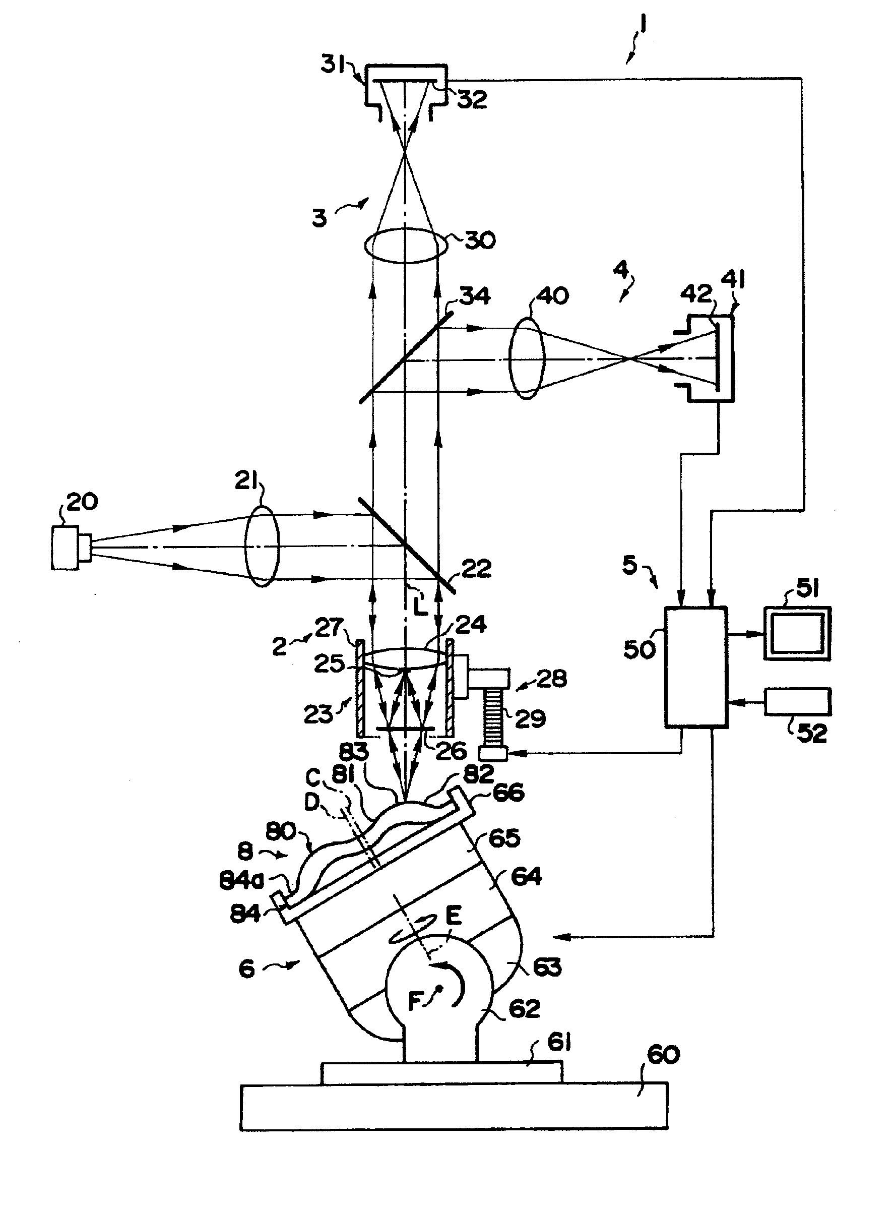
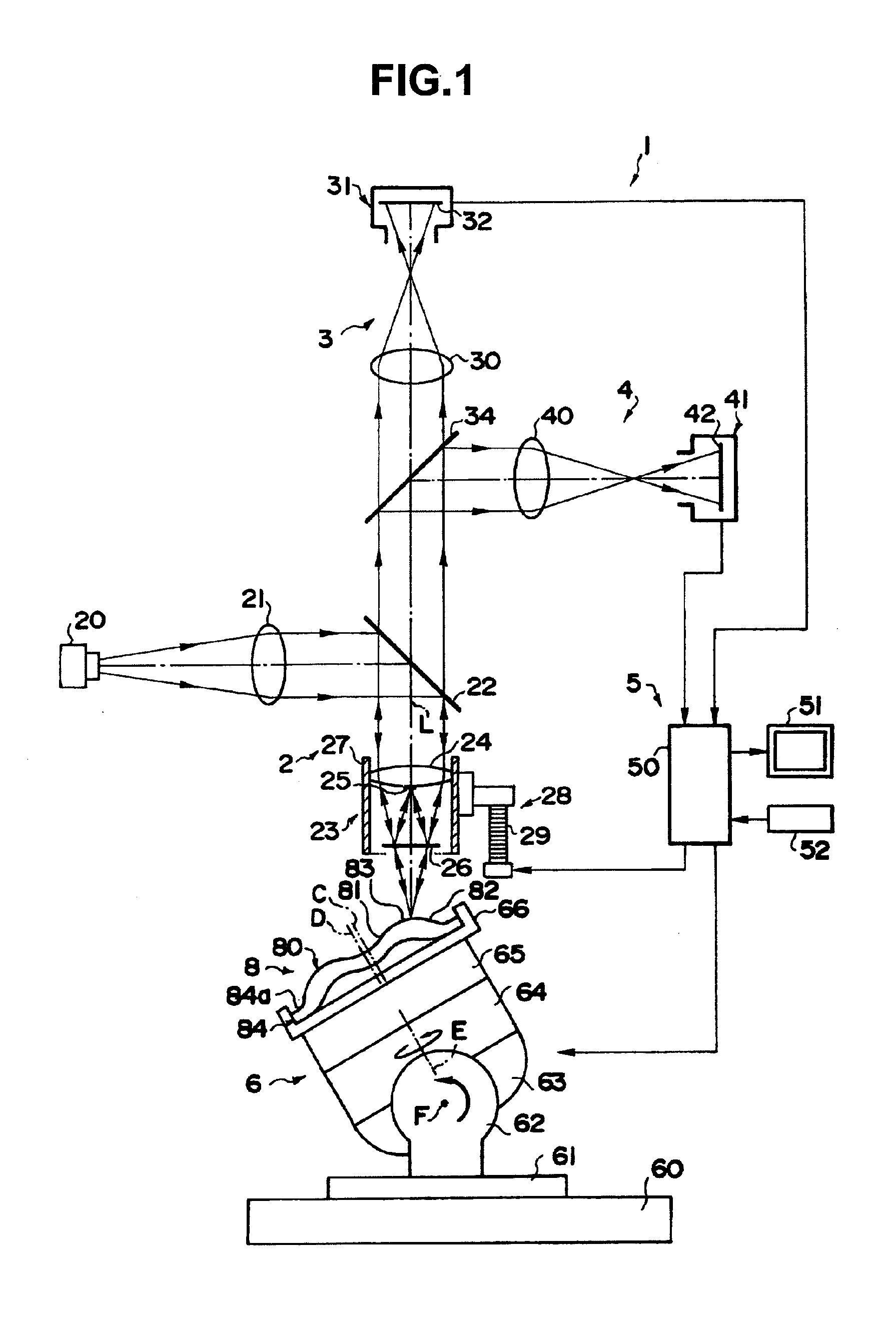
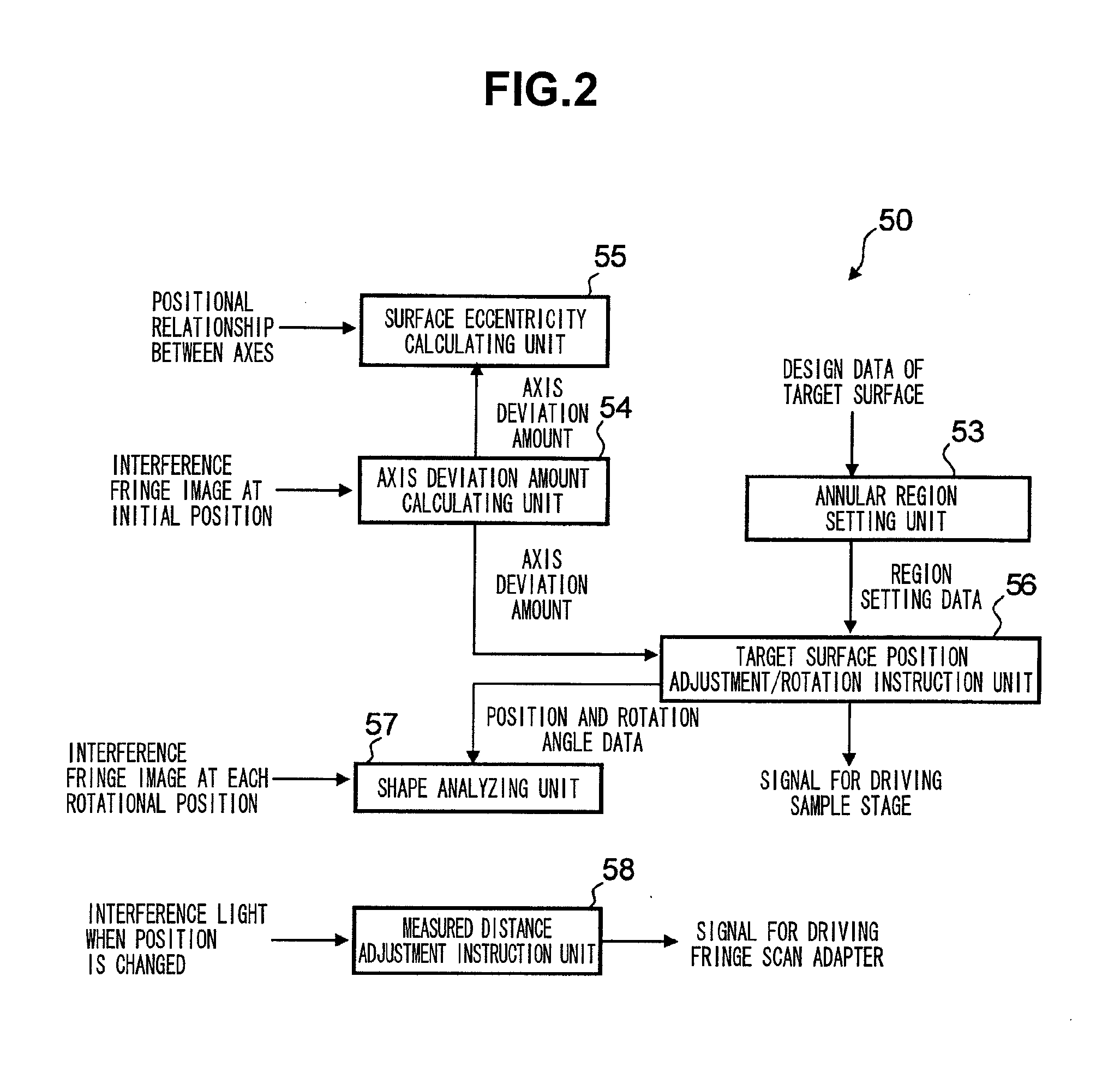
[0029]Hereinafter, exemplary embodiments of the invention will be described in detail with reference to the accompanying drawings. FIG. 1 is a diagram schematically illustrating the structure of an optical wave interference measuring apparatus according to an embodiment of the invention, and FIG. 2 is a block diagram illustrating the structure of an analysis control device shown in FIG. 1. The diagrams used to describe the embodiments schematically show components, but do not show the detailed shapes or structures of the components. In particular, in FIG. 1, for example, the size of each member or the distance between the members is appropriately changed.

[0030]The optical wave interference measuring apparatus 1 according to this embodiment shown in FIG. 1 measures and analyzes the shape of a test surface 80 of a test lens 8 (a test object in this embodiment) (an upper lens surface of the test lens 8 in FIG. 1) that has a small diameter of about several millimeters and is rotationall...


PUM


Abstract

The relative position of a test surface is sequentially changed from a reference position where a surface central axis is aligned with a measurement optical axis such that the measurement optical axis is sequentially moved to a plurality of annular regions obtained by dividing the test surface in a diametric direction. The test surface is rotated on a rotation axis whenever the relative position is changed. Measurement light that travels while being converged by a Mirau objective interference optical system is radiated to the rotating test surface, and a one-dimensional image sensor captures interference fringes at each of a plurality of rotational positions. The shape information of each annular region is calculated on the basis of the captured interference fringes at each rotational position, and the shape information is connected to calculate the shape information of the entire measurement region.

Description

CROSS-REFERENCE TO RELATED APPLICATIONS[0001]This application is based upon and claims the benefit of priority from the Japanese Patent Application No. 2008-270151 filed on Oct. 20, 2008 and the Japanese Patent Application No. 2009-207890 filed on Sep. 9, 2009; the entire contents of which are incorporated herein by reference.BACKGROUND OF THE INVENTION[0002]1. Field of the Invention[0003]The present invention relates to an optical wave interference measuring apparatus that radiates measurement light to a test surface and measures the shape of the test surface on the basis of an interference fringe formed by interference between reference light and returning light from the test surface, and more particularly, to an optical wave interference measuring apparatus suitable for a small test surface that is rotationally symmetric and has a complicated shape.[0004]2. Description of the Related Art[0005]A method has been proposed which radiates spherical waves to an aspheric test surface an...

Claims


Application Information

Patent Timeline
IPC IPC(8): G01B11/02
CPCG01B11/2441G01M11/0271G01M11/025
Inventor GE, ZONGTAOKANDA, HIDEOSAITO, TAKAYUKIKOIZUMI, NOBORU
Owner FUJI PHOTO OPTICAL CO LTD
Why Eureka
Try Eureka