
Golf Bag Cart

Inactive Publication Date: 2010-04-15
UNIQUE PRODS & DESIGN
View PDF46 Cites 16 Cited by
  • Summary
  • Abstract
  • Description
  • Claims
  • Application Information

AI Technical Summary

Benefits of technology

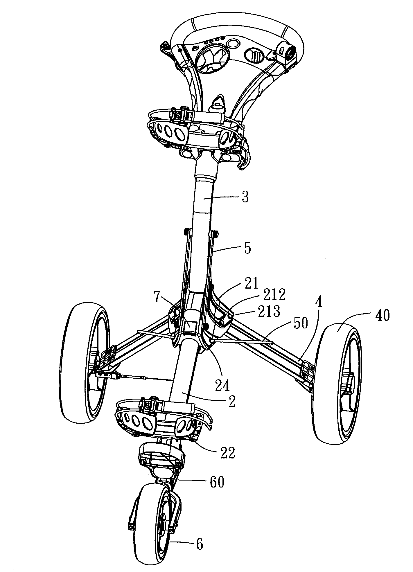
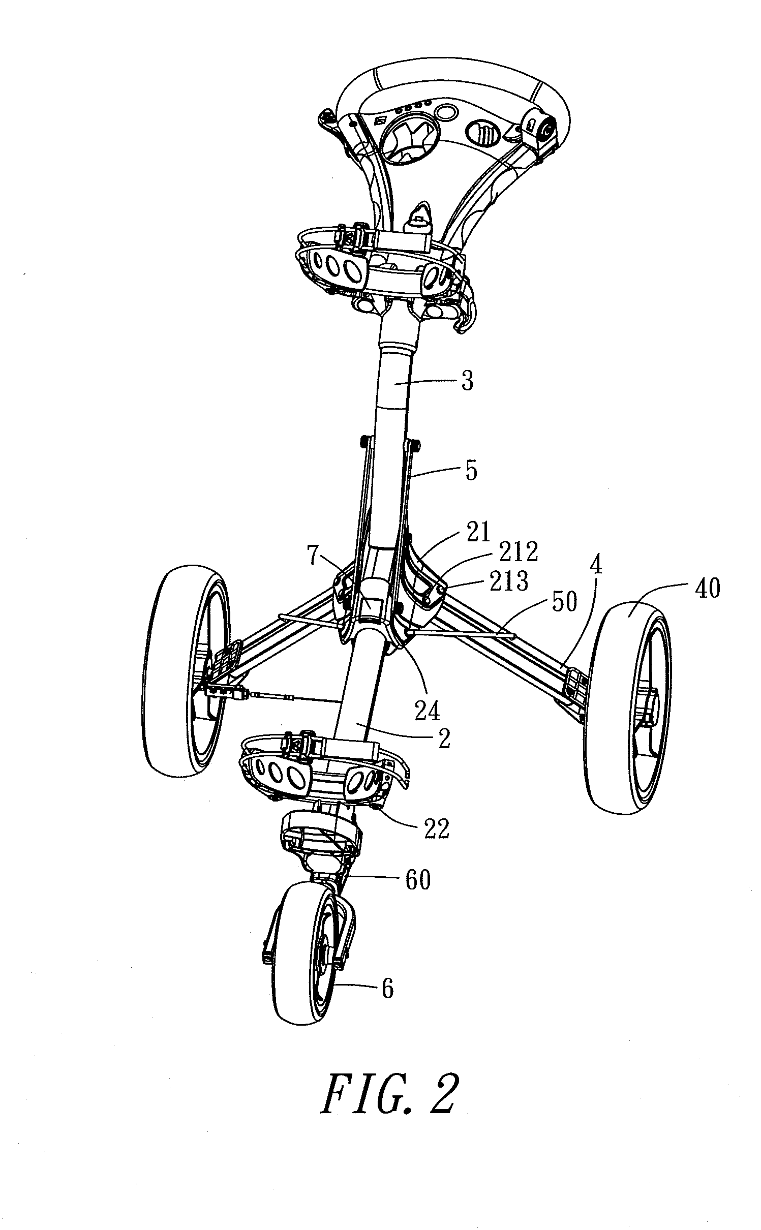
[0008]To accomplish the aforesaid objective, the present invention comprises: a bottom cart stand, having a link segment at its top, and a bag base at its bottom, where the bottom cart stand is provided with a slider thereon; an upper cart stand, in pinned connection with the link segment at its bottom; a rear wheel frame, fixed at each of both sides of the link segment, where the two rear wheel frames and the bottom cart stand together form a pyramid, and the bottom end of the rear wheel frame connects to the rear wheel; a linkage, set up between the upper cart stand and the slide, to link the upper cart stand physically to the slider; a draw pole, set up between the slide and the rear wheel frame, to link the slider physically to the rear wheel frame; a front wheel, positioned under the bag base, having a folding joint, which could level the front wheel; and a lock mechanism, having a core, in pinned connection to the top of the slider, where the upper cart stand and the bottom cart stand are thus fastened to each other; by way of the above structural combination, the folding operation is carried out by releasing the lock mechanism, twisting the upper cart stand and the bottom cart stand to put together closely, and leveling the front wheel; whereas the unfolding operation requires the slider to slide toward the link segment subject to the linking of the linkage, the slider, the draw pole and the rear wheel frame, and the upper cart stand and the bottom cart stand are fastened to each other through the use of the lock mechanism, followed by spreading up the rear wheels; the pyramid, formed by the two rear wheel frames and the bottom cart stand, supports the cart to stand up on the ground, which sufficiently holds the load in the bag, to keep the cart sustainable and to avoid deforming into collapse.

Problems solved by technology

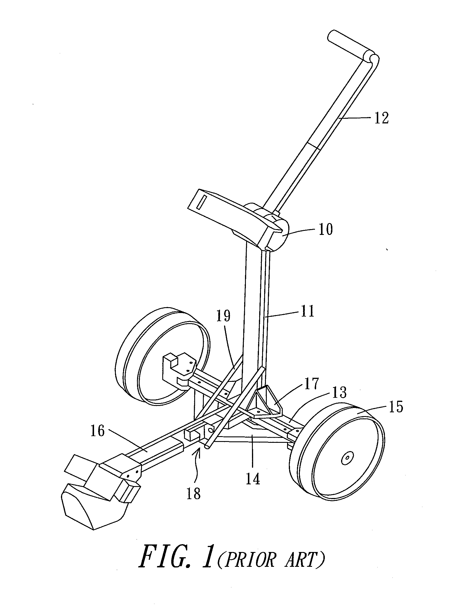
Once the golf bag is loaded on the cart and the horizontal bottom cart stand 16 lacks of any load supports in design, the bottom cart stand 16 would sink into deformation, which will further damage the cart frame.

Method used


Image

  • Golf Bag Cart
  • Golf Bag Cart
  • Golf Bag Cart

Examples


Embodiment Construction

[0018]The structural traits and the functioning of the present invention are detailed described with reference to the following preferred exemplified embodiment and the accompanying drawings, which helps the honorable Examiner to have a thorough comprehension and recognition.

[0019]Referring to FIGS. 2-6, the figures show the structure of the golf bag cart is symmetric on the left and the right. In favor of comprehension, the following description is subject to merely a single side of the structure.

[0020]The present invention comprises: a bottom cart stand 2, having a central link segment 21 at its top and a bag base 22 at its bottom, where the bottom cart stand 2 is provided with a trench 23 at each of the two sides near the link segment 21, for the accommodation of a slider 24, and the bottom cart stand 2 is provided with a spring 25 hidden in its internal, where its one end is joined fixedly to the link segment 21, while the other end to the slider 24; an upper cart stand 3, in pi...


PUM


Abstract

A golf bag cart is disclosed, comprising a bottom cart stand, having a link segment at its top, and a bag base at its bottom, where the bottom cart stand is provided with a slider thereon; an upper cart stand, in pinned connection with the link segment at its bottom; a rear wheel frame, fixed at each of both sides of the link segment, where the two rear wheel frames and the bottom cart stand together form a pyramid, and the bottom end of the rear wheel frame connects to the rear wheel; a linkage, set up between the upper cart stand and the slide; a draw pole, set up between the slide and the rear wheel frame; a front wheel, positioned under the bag base, having a folding joint, which could level the front wheel; and a lock mechanism, having a core, in pinned connection to the top of the slider, where the upper cart stand and the bottom cart stand are thus fastened to each other; the rear wheels could be spread up, subject to the linking among the linkage, the slider, the draw pole and the rear wheel frame; through the pyramid, formed by the two rear wheel frames and the bottom cart stand, the cart is able to stand up on the ground with better backing, which sufficiently holds the bag load, to keep the cart sustainable and to avoid deforming into collapse.

Description

BACKGROUND OF THE INVENTION[0001]1. Field of the Invention[0002]This invention relates generally to golf bag carts and more specifically to a structure characterizing a rock-steady frame, scarcely deforming into collapse.[0003]2. Description of the Prior Art[0004]Prior art golf bag carts have a common structure in FIG. 1, where the upper tube 11 and the handle bar 12 are provided with a joint mechanism 10 in between, and the bottom end of the upper tube 11 and the connecting mount 17 are linked each other. The connecting mount 17 is further linked to the bottom cart stand 16 and the wheel frame 13. The bottom cart stand 16 is provided with a slider 18, which could join the upper tube 11 by a vertical draw bar 19, enabling the link between the upper tube 11 and the slider 18. A crosswise draw bar 14, set up physically between the wheel frame 13 and the slider 18, drives the two rear wheels to fold inwardly the moment that the upper tube 11 is being folded.[0005]The wheel frame 13 and...

Claims


Application Information

Patent Timeline
IPC IPC(8): A63B55/08A63B55/60
CPCB62B2202/404B62B3/12
Inventor LIAO, GORDON
Owner UNIQUE PRODS & DESIGN
Learn More