
Combined optical cable distribution cabinet

A combined type and wiring box technology, applied in the direction of fiber mechanical structure, etc., can solve the problems of reduced water resistance and safety of the box, poor waterproof effect of the box, troublesome assembly process of the box, etc., to achieve cost saving and waterproof The effect is ideal and the effect of strengthening the firmness

Inactive Publication Date: 2011-02-23
宁波华缘复合新材料有限公司
View PDF3 Cites 2 Cited by
  • Summary
  • Abstract
  • Description
  • Claims
  • Application Information

AI Technical Summary

Problems solved by technology

[0006] First of all, each set of fasteners includes two screws and a connecting iron piece. When assembling the box, the screws must be tightened twice to fix a set of fasteners. In this way, the entire box assembly process is cumbersome, and each set of fasteners must be tightened twice. Firmware needs to consume iron parts and two screws, which increases the production cost of the box; secondly, when locking or opening the lock on the door, the two latches are easy to break the door frame when moving up and down. If the hanging is broken, the service life of the door frame will be shortened. Moreover, when locked, the latch and the door frame will not be tightly contacted, so that the door can still swing in a small range relative to the door frame, resulting in a reduction in the waterproofness and safety of the entire cabinet; again , because the two side panels, the door frame, and the rear panel are all fixed to the lower panel by two sets of fasteners, so although the two side panels, the door frame, and the rear panel are fastened to the fasteners, the two sets of the above parts The position between the fasteners is not strong enough, and it is easy to deform under the action of external force, so that the two side panels, door frames or rear panels collapse toward the middle; The firmware is fixed to the upper plate, so that the two side panels, door frames or rear panels will also have the disadvantage of collapsing in the middle; finally, because the box is assembled, there will inevitably be gaps between the parts, which will lead to the entire box. The body is not waterproof

Method used


Image

  • Combined optical cable distribution cabinet
  • Combined optical cable distribution cabinet
  • Combined optical cable distribution cabinet

Examples


Embodiment Construction

[0045] The present invention will be further described below in conjunction with the accompanying drawings and specific embodiments.

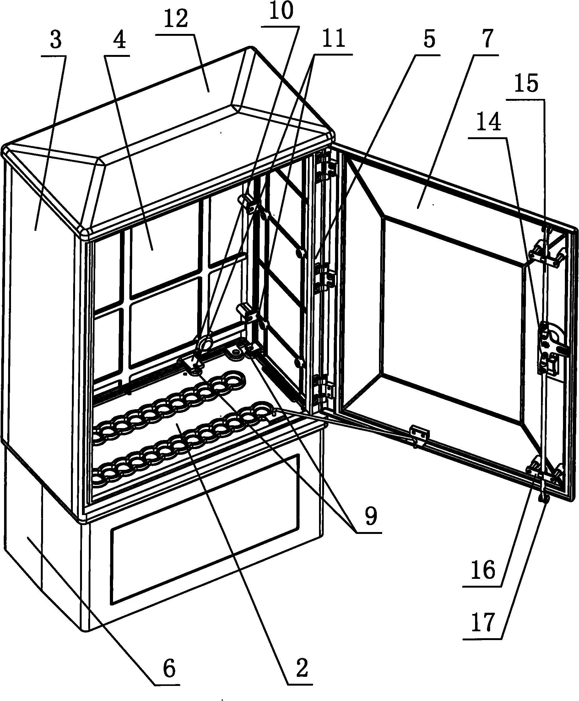
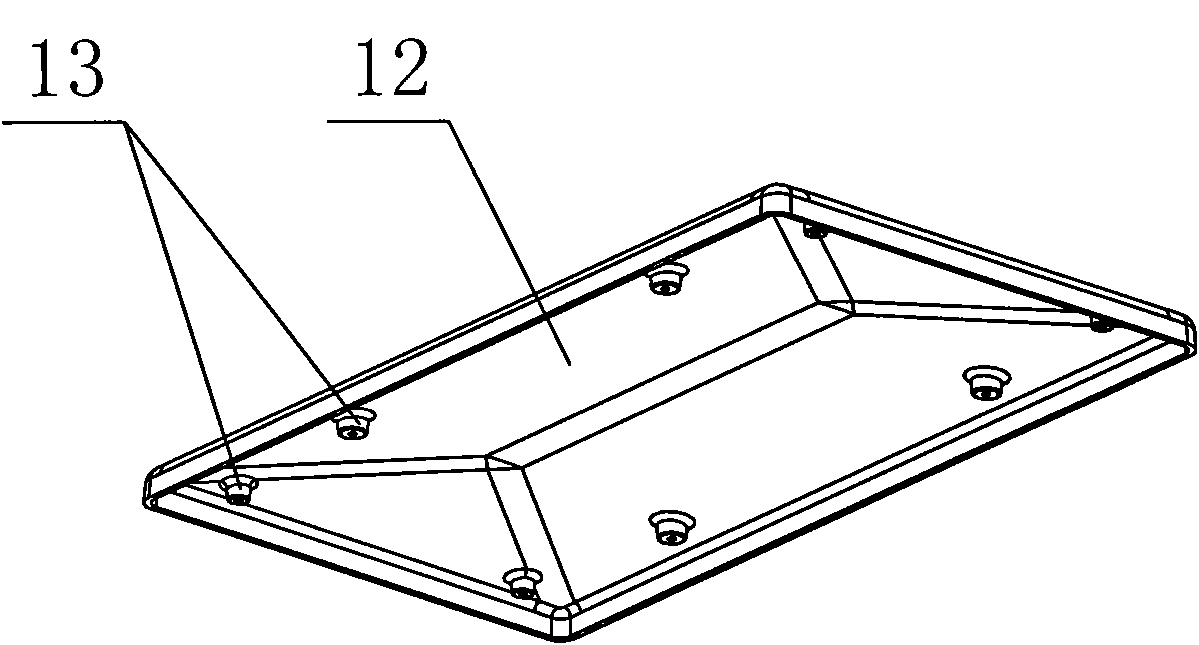
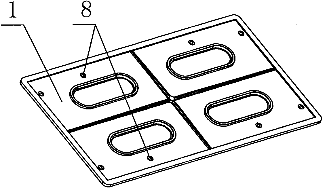
[0046] Such as figure 1 , figure 2 , image 3 , image 3 , Figure 4 , Figure 5 , Image 6 , Figure 7 , Figure 8 , Figure 9 , Figure 10 , Figure 11 , Figure 12 , Figure 13 , Figure 14 , Figure 15 , Figure 16 As shown, the combined optical cable distribution box of the present invention includes an upper board 1, a lower board 2, left and right side boards 3, a rear board 4 and a door frame 5, and every two of the above six parts are adjacent and vertical Components are secured with complete sets of fasteners. A door 7 is hinged on the door frame 5, and a lock is provided between the door 7 and the door frame 5. Each set of fasteners includes a screw, a fixing seat 9 with a threaded hole 8 and a mounting seat 10 with a groove 11 corresponding to the threaded hole 8, and the screw passes through the groove 11 of the m...


PUM


Abstract

The invention discloses a combined optical cable distribution cabinet, which comprises upper and lower plates (2), left and right side plates (3), a rear plate (4) and a doorframe (5), wherein every two adjacent and vertical components among the six components are fixed by a matched fastening piece. A door (7) is hinged on the doorframe (5); a lock is arranged between the door (7) and the doorframe (5); each set of fastening pieces comprise a bolt, a fixing base (9) with a threaded hole and a mounting base (10) with a groove (11) or hole corresponding to the threaded hole; and the bolt passes through the groove (11) or hole of the mounting base (10) to be screwed with the threaded hole of the fixing base (9). The combined optical cable distribution cabinet is convenient to assemble and is low in manufacturing cost.

Description

technical field [0001] The invention relates to the field of communication equipment, in particular to a combined optical cable distribution box. Background technique [0002] The combined optical cable distribution box is a box that connects, distributes, dispatches and protects the main optical cable and branch optical cable in the optical cable network. The box is generally made of glass fiber reinforced plastic. [0003] The combined optical cable distribution box in the prior art includes an upper board, a lower board, two side boards, a rear board and a door frame, and every two adjacent and vertical parts of the above six parts are fixed by a complete set of fasteners Each set of fasteners includes two screws and a connecting iron piece (angle steel). The connecting iron piece is composed of two iron sheets that are perpendicular to each other and are integrated. The specific fixing method of the firmware is that one screw is screwed into the threaded hole of the fix...

Claims


Application Information

Patent Timeline
IPC IPC(8): G02B6/44
Inventor 詹德泽
Owner 宁波华缘复合新材料有限公司
Learn More