Circuit board mounting structure and contactor

A technology of installation structure and circuit board, which is applied in the direction of circuits, relays, electromagnetic relays, etc., can solve problems such as product failure, and achieve the effects of good insulation performance, reliable connection, and easy assembly and disassembly

Pending Publication Date: 2021-04-02
ZHEJIANG TENGEN ELECTRIC
View PDF0 Cites 2 Cited by
  • Summary
  • Abstract
  • Description
  • Claims
  • Application Information

AI Technical Summary

Problems solved by technology

[0006] The technical problem to be solved by the present invention is to overcome the problem that the circuit board in the prior art is set facing the double coil winding, and the wire needs to be reserved long enough to cause friction between the wire and the double coil winding. Technical problems that cause product failure, thereby providing a circuit board mounting structure that can prevent product failure and a contactor with the circuit board mounting structure

Method used


Image

  • Circuit board mounting structure and contactor
  • Circuit board mounting structure and contactor
  • Circuit board mounting structure and contactor

Examples


Embodiment 1

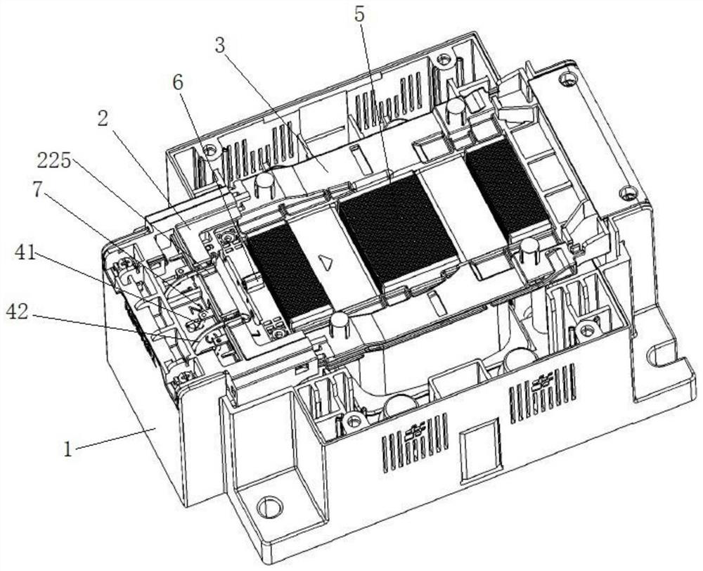
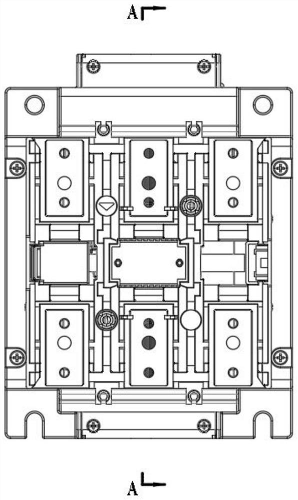
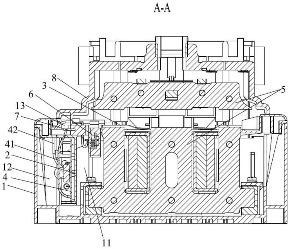
[0070] The circuit board mounting structure of this embodiment, see Figure 1 to Figure 10 As shown, it includes a base 1 , a base 8 , a bobbin 3 , a double coil winding 5 , a case 2 , a circuit board 4 , a switching module 6 , a first wire 41 and a second wire 42 . The bobbin 3 is used to fix the double coil winding 5, on which the lug 7 is fixed. The body shell 2 is suitable for connecting with one end of the coil frame 3 for mounting the circuit board 4 . The switching module 6 is used to control the switching of the double coil winding 5, and is fixed on the bobbin 3, specifically as Figure 4 As shown, the switching module 6 is located between the double coil winding 5 and the body case 2 . Such as Figure 4 As shown, the circuit board 4 is installed on the end of the casing 2 facing away from the double coil winding 5 . Such as image 3 As shown, the first wire 41 is used to connect the circuit board 4 and the lug 7 on the coil frame 3 , and the second wire 42 is us...

Embodiment 2

[0076] The contactor of this embodiment, such as Figure 10 As shown, it includes the circuit board installation structure in Embodiment 1 and the fire extinguishing system 9 arranged above the base 1 and the base 8, and the fire extinguishing system 9 includes an arc extinguishing cover and an arc extinguishing plate assembly. The specific structure of the arc extinguishing plate assembly is not described and limited in detail here, and it is an existing conventional structure. Since the above-mentioned circuit board installation structure is adopted, at least the advantages of the circuit board installation structure of the above-mentioned embodiment 1 are provided, and details will not be repeated here.


PUM


Abstract

The invention relates to the technical field of contactors, in particular to a circuit board mounting structure and a contactor. The circuit board mounting structure comprises a coil framework used for fixing a double-coil winding, wherein a lug plate is fixed on the coil framework; a shell is suitable for being connected with one end of the coil framework and used for installing a circuit board;a circuit board is mounted at one end, opposite to the double-coil winding, of the shell; a switching module is used for controlling switching of the double-coil winding, is fixed on the coil framework and is positioned between the shell and the double-coil winding; one end of the first wire is welded and fixed on the circuit board, and the other end passes through the shell and is connected withthe lug plate; and the second wire is used for coupling the switching module with the circuit board. The circuit board mounting structure is advantaged in that interference and friction between the wire and the double-coil winding are avoided, and product failure can be effectively prevented.

Description

technical field [0001] The invention belongs to the technical field of contactors, and in particular relates to a circuit board installation structure and a contactor. Background technique [0002] A contactor is an electrical appliance used for long-distance and frequent switching on and off of AC and DC main circuits and large-capacity control circuits. Its main control object is the motor, and it can also be used to control electric heating equipment, electric lighting, and electric welding machines. and electrical loads such as capacitor banks. The contactor has a high operating frequency, the highest operating frequency can reach 1200 times per hour. In the circuit, the contactor is not required to have the ability to break the short-circuit current. When the circuit is short-circuited, it is protected by a fuse or a circuit breaker connected in series with the contactor. [0003] Contactors are divided into high-voltage and low-voltage contactors according to voltage...

Claims


Application Information

Patent Timeline
Patent Type & Authority Applications(China)
IPC IPC(8): H01H50/04H01H50/44
CPCH01H50/04H01H50/44H01H50/443H01H2050/446
Inventor 李辉荣良章计新华马荣贵张红伟陈林
Owner ZHEJIANG TENGEN ELECTRIC
Why Eureka
Try Eureka