
Full frequency scanning method and channel parameter adjusting method for smart antenna

a technology of smart antennas and channel parameters, applied in the direction of radio transmission, transmission, substation equipment, etc., can solve the problems of consuming unavoidably much time, restricting the system capacity of wireless communication systems, and affecting the efficiency of search operations, so as to achieve automatic tuning of optimal parameters of communication channels, saving effective time spen

Active Publication Date: 2010-04-08
ALICORP
View PDF6 Cites 26 Cited by
  • Summary
  • Abstract
  • Description
  • Claims
  • Application Information

AI Technical Summary

Benefits of technology

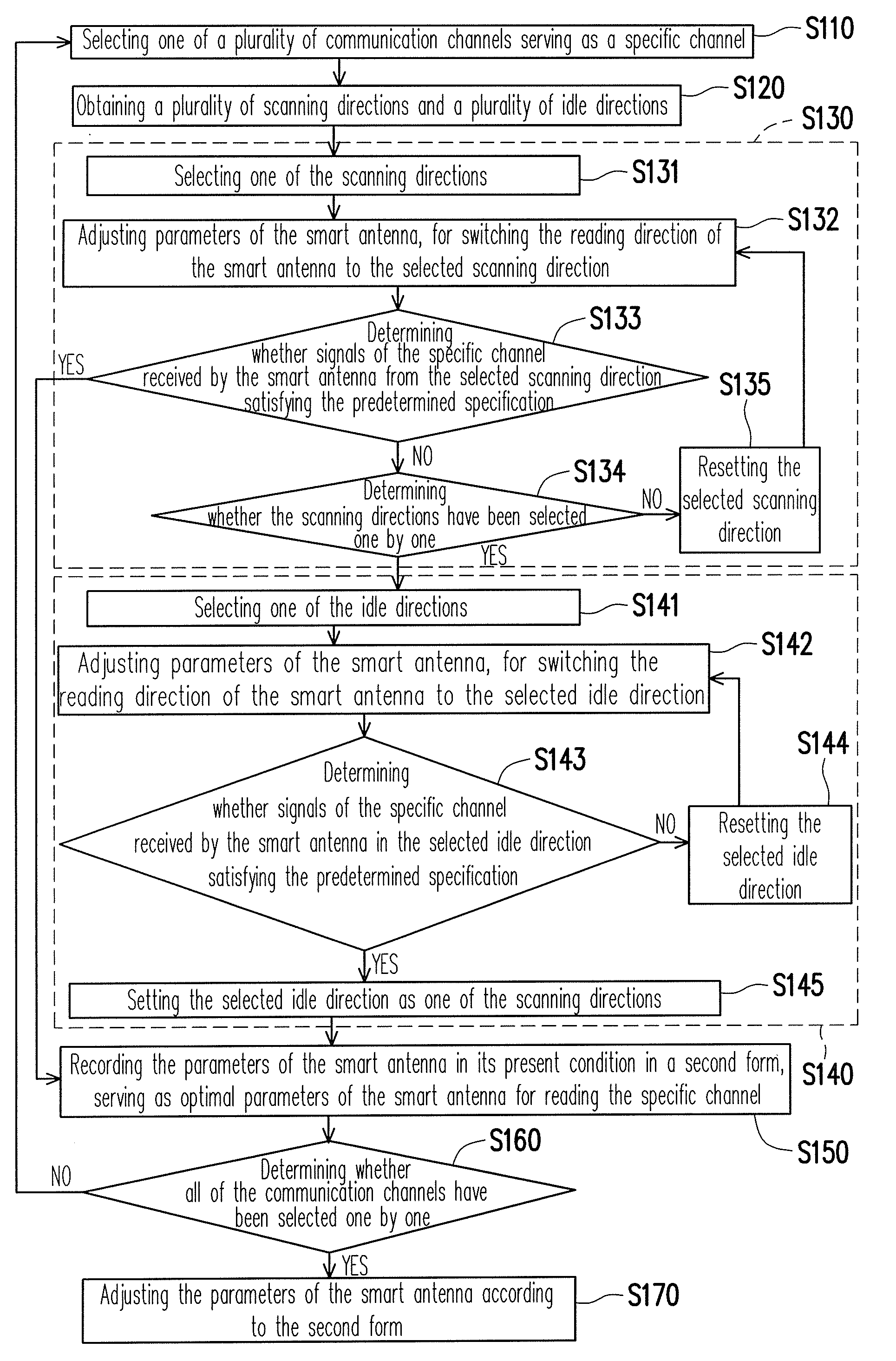
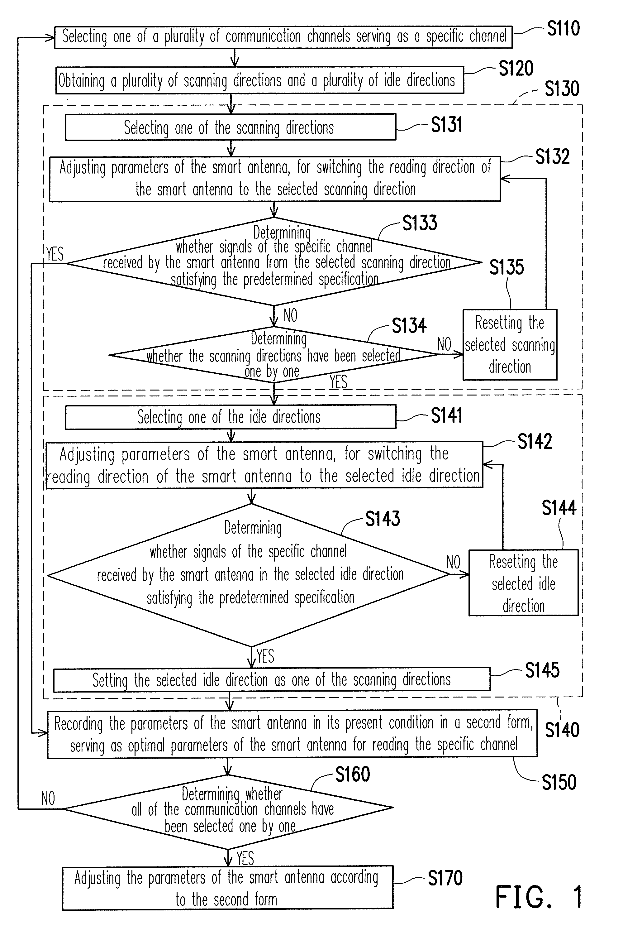
The present invention provides an adjusting method for a smart antenna that saves time and automatically tracks the status of communication channels. The method includes obtaining a plurality of scanning directions and idle directions, adjusting the reading direction of the smart antenna based on the scanning directions, and comparing signals of a specific channel with a predetermined specification. The method also includes recording optimal parameters for specific channels based on the signals of the channels and parameters of the smart antenna, and adjusting the parameters of the smart antenna based on the second form and deviation parameters. The invention allows for efficient and effective saving of time and automatic tuning of optimal parameters for communication channels.

Problems solved by technology

Generally, omni-directional antennas and directional antennas are often interfered by multipath and co-channel signals, which disturb the transmission and restrict the system capacity of the wireless communication system.
However, such a searching process unavoidably consumes much time.
Further, the smart antenna is also often affected by environmental variation or changed as time going by.

Method used


Image

  • Full frequency scanning method and channel parameter adjusting method for smart antenna
  • Full frequency scanning method and channel parameter adjusting method for smart antenna
  • Full frequency scanning method and channel parameter adjusting method for smart antenna

Examples


Embodiment Construction

[0027]Reference will now be made in detail to the present preferred embodiments of the invention, examples of which are illustrated in the accompanying drawings. Wherever possible, the same reference numbers are used in the drawings and the description to refer to the same or like parts.

[0028]FIG. 1 is a flow chart illustrating a part of an adjusting method of a smart antenna according to an embodiment of the present invention. Referring to FIG. 1, optimal parameters of each of a plurality of communication channels are obtained by executing step S110 through S160. Thereafter, the smart antenna can then be operated with the optimal parameters, thus achieving an improved signal receiving performance as desired.

[0029]Generally, the present invention searches a plurality of communication channels one by one. For example, if an operable frequency range of the smart antenna is 470 to 860 MHz and a frequency bandwidth for transmission is 6 MHz, the smart antenna will search 65 communicatio...


PUM


Abstract

An adjusting method for a smart antenna is provided. The adjusting method divides all possible reading directions of the smart antenna into a plurality of scanning directions and a plurality of idle directions by a first form. In searching for the optimal parameters of each of a plurality of communication channels, the adjusting method firstly adjusts the reading direction according to the plurality of scanning directions, and then adjusts the reading direction according to the plurality of idle directions. Further, the first form remain updated in accordance the process of searching for the optimal parameters of each of the communication channels, thus effectively saving the time spent on the full frequency scanning process. Further, the optimal parameters of each of the communication channels are recorded in a second form, so that the smart antenna is regulated according to the second form.

Description

CROSS-REFERENCE TO RELATED APPLICATION[0001]This application claims the priority benefit of Chinese application serial no. 200810149838.1, filed on Oct. 8, 2008. The entirety of the above-mentioned patent application is hereby incorporated by reference herein and made a part of this specification.BACKGROUND OF THE INVENTION[0002]1. Field of the Invention[0003]The present invention generally relates to an adjusting method for a smart antenna, and more particularly, to an adjusting method adapted for saving a time spend by a smart antenna on a full frequency (channel) searching.[0004]2. Description of Related Art[0005]As the electronic science and technology being progressively developed, people have now become used to wireless communication. Therefore, an antenna often plays a key role in a wireless communication system, and even may be a critical part determining the overall performance of the system. Generally, omni-directional antennas and directional antennas are often interfered...

Claims


Application Information

Patent Timeline
Patent Type & Authority Applications(United States)
IPC IPC(8): H04B1/18
CPCH01Q1/1257
Inventor CHEN, CHIEN-TSUNKUO, TIEN-HSIN
Owner ALICORP
Learn More