
Induction connecting sleeve for connecting weldable thermoplastic elements by means of fusion

a technology of induction connecting sleeve and thermoplastic element, which is applied in the direction of pipe connection arrangement, mechanical working/deformation, lamination, etc., can solve the problems of insufficient contact pressure, and increased cost of excitation devi

Inactive Publication Date: 2010-04-08
LEISTER TECHNOLOGIES
View PDF1 Cites 7 Cited by
  • Summary
  • Abstract
  • Description
  • Claims
  • Application Information

AI Technical Summary

Benefits of technology

[0010]The direction of the pre-tension of the induction heating element is selected to be the opposite of the desired direction of the required contact pressure, which causes the tension of the induction heating element to relax in the direction of the fusion connection zone. Due to the pressure of the induction heating element exerted towards the connection section of the thermoplastic element, the melted thermoplastic material of the socket that faces the thermoplastic element is pressed against the connection section of the thermoplastic element which securely closes the annular gap between the socket and the connection section.
[0013]A good mechanical alignment of the connection section relative to the socket, and a good mechanical connection of the connection section relative to the socket result when the socket overlaps a wall of the connection sections on both sides, and is fused with these on both sides. With an induction connecting sleeve of this design, the induction heating element is advantageously designed so that it also overlaps the wall on both sides, with its pre-tension being the opposite on the two sides.
[0015]In a preferred embodiment of the invention, the induction heating element comprises a strip of material deformed into a cylinder, where an axial longitudinal gap is formed between its facing edges. By enlarging or reducing this longitudinal gap, the induction heating element can be radially pre-tensioned in a simple manner. In addition, an induction heating element of this type is especially easy and inexpensive to produce.
[0016]In another preferred embodiment of the invention, the induction heating element comprises a closed cylinder section followed by an axially slotted cylinder section with laminae with radial spring action. A high mechanical radial stability of the induction heating element is achieved by the closed cylinder section. The laminae with radial spring action of the slotted cylinder section may be pre-tensioned radially towards the inside or the outside. It is also possible to provide a corresponding axially slotted cylinder section on both sides of the closed cylinder section.
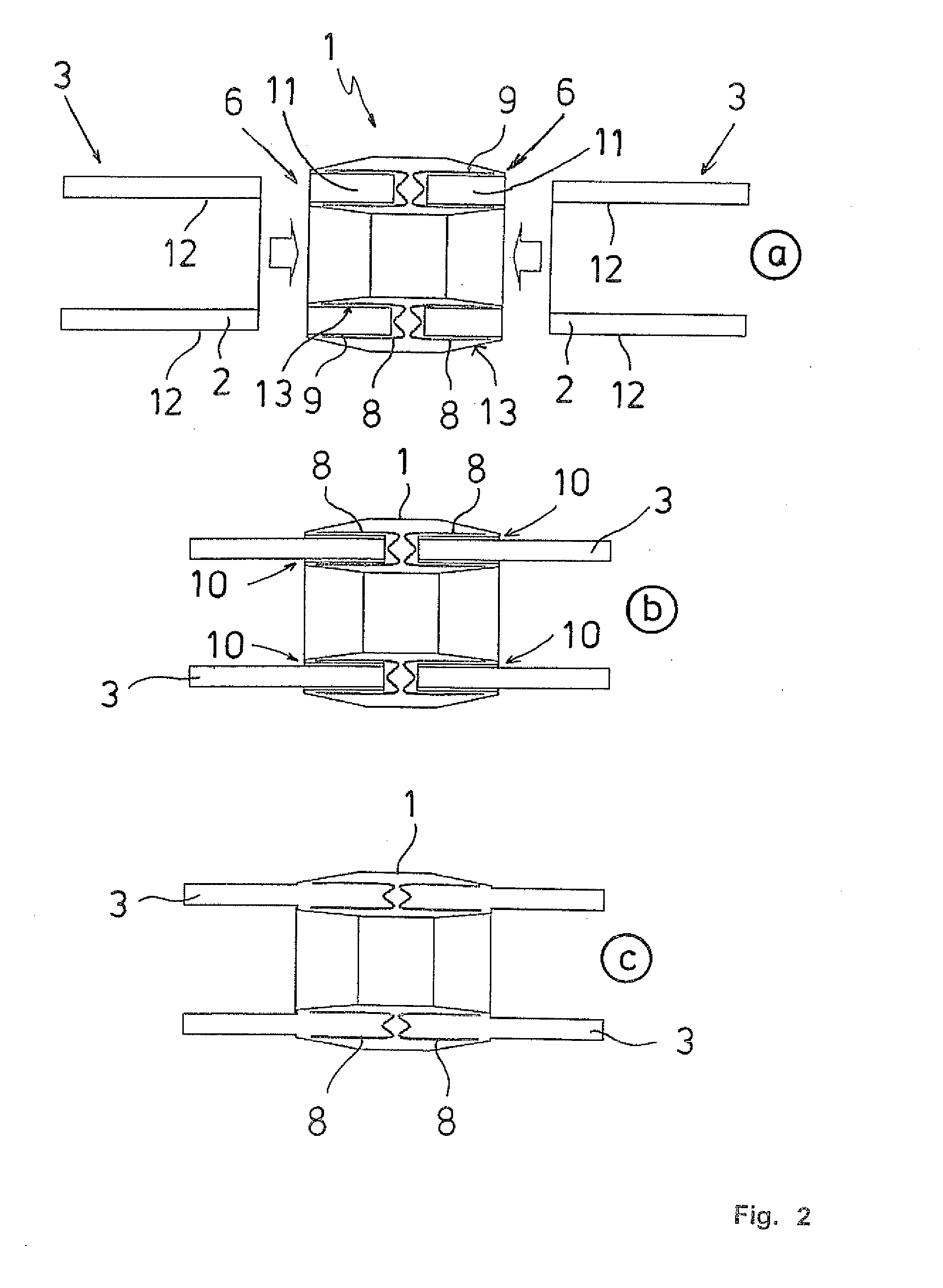
[0017]In one embodiment of the induction connecting sleeve according to the invention, at least two induction heating elements are arranged in the socket, with axial spacing. In this way, the socket can be fused with the associated connection section at several, axially successive points; this has an advantageous effect on the mechanical attachment of the thermoplastic element to the connecting sleeve as well as on the seal between the socket and the connection section when, due to different expansion coefficients, the materials react differently when cooling.

Problems solved by technology

In contrast, the excitation devices for an induction connecting sleeve with a ferromagnetic plastic matrix are considerably more costly.
This requires considerably higher frequencies in the megahertz range that make the excitation devices more expensive.
Common plastic tubes are manufactured in an extrusion process with large manufacturing tolerances so that the required contact pressure is not ensured even with precision-made induction connecting sleeves.

Method used


Image

  • Induction connecting sleeve for connecting weldable thermoplastic elements by means of fusion
  • Induction connecting sleeve for connecting weldable thermoplastic elements by means of fusion
  • Induction connecting sleeve for connecting weldable thermoplastic elements by means of fusion

Examples


Embodiment Construction

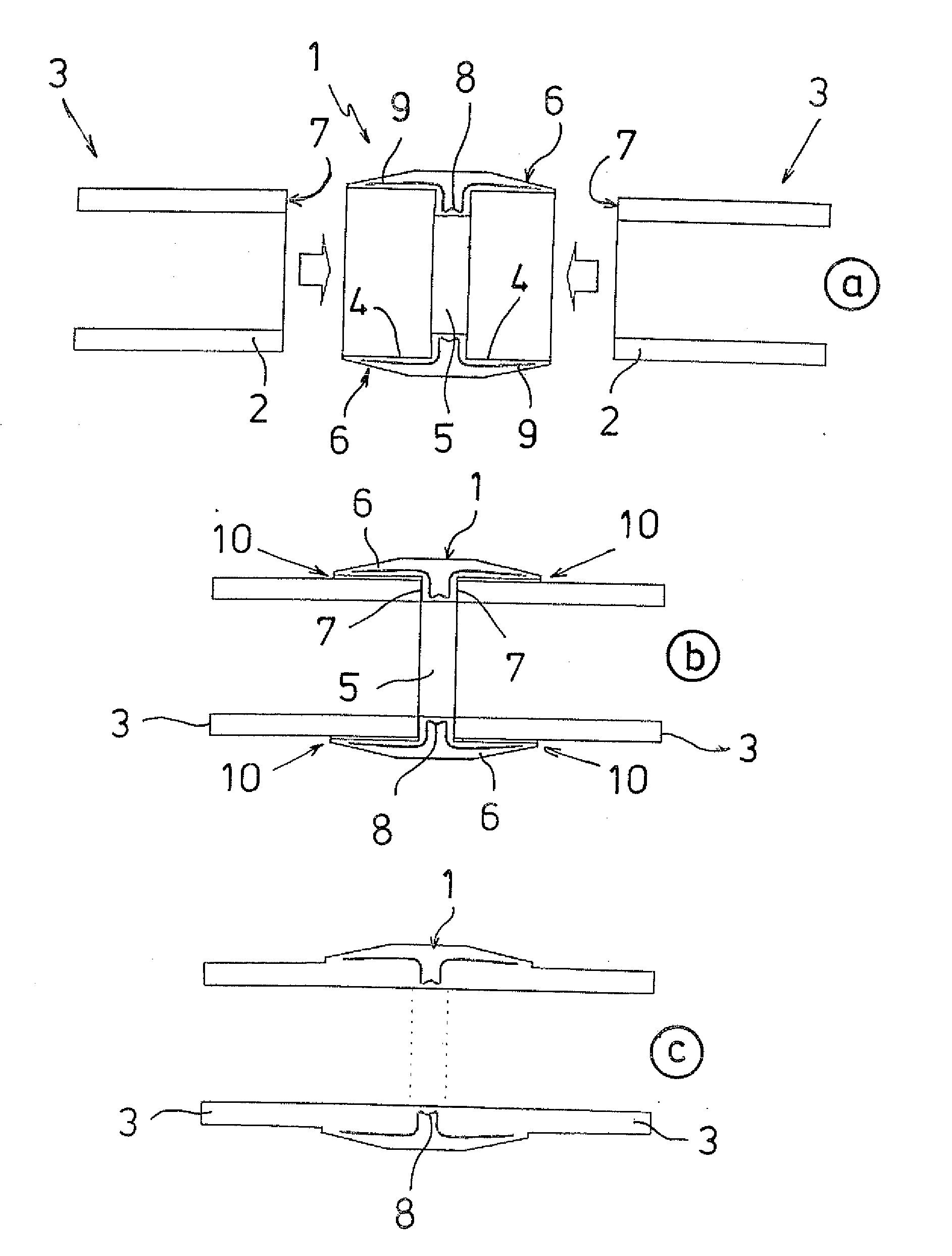
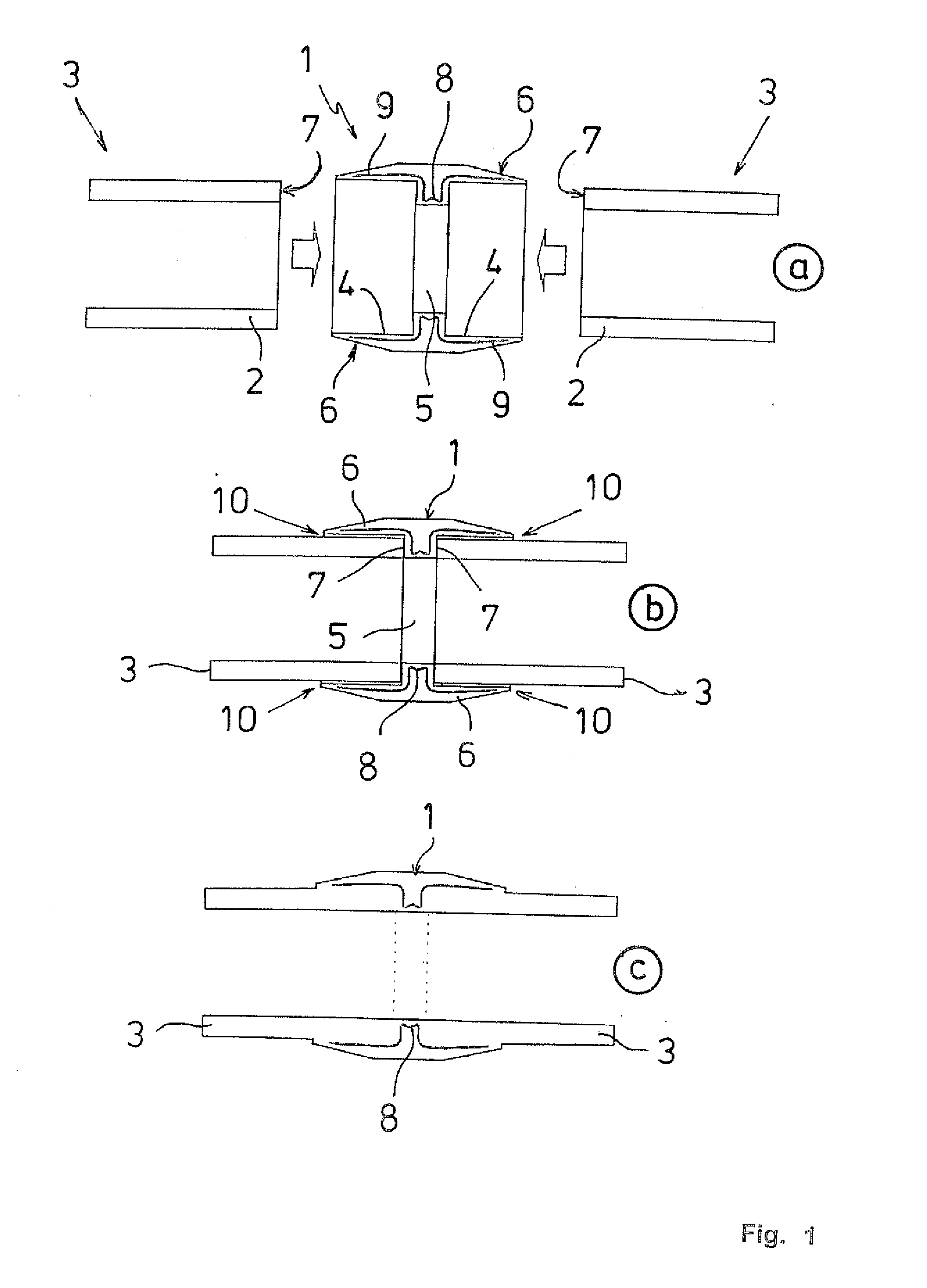
[0023]In FIG. 1a, FIG. 1 shows the first induction connecting sleeve 1 according to the invention. In FIG. 1b, connection sections 2 of thermoplastic elements 3 in the form of plastic tubes that are to be connected are inserted in the connecting sleeve 1. In FIG. 1c, the plastic tubes 3 are fused with the induction connecting sleeve 1. The induction connecting sleeve 1 has essentially the form of a hollow cylinder with an annular flange 5 protruding from the inner circumferential surface 4 that encloses at the face side two sockets 6 for accepting the connection sections 2. The annular flange 5 serves to butt-join the front faces 7 of the connection sections 2.

[0024]Into the thermoplastic plastic material of the induction connecting sleeve 1, an induction heating element 8 shaped similar to a bushing and made of a metallic material with spring characteristics is embedded and is arranged coaxially to the sockets 6 and centered between the sockets 6. End sections 9 of the induction he...


PUM

PropertyMeasurementUnit
Pressureaaaaaaaaaa
Tensionaaaaaaaaaa
Weldabilityaaaaaaaaaa

Abstract

An induction connecting sleeve for connecting weldable thermoplastic elements by means of fusion, with at least two sockets for the insertion of connection sections of the thermoplastic elements to be connected, and with an induction heating element embedded in the sockets, with operative sections of the induction heating element surrounded completely by a weldable thermoplastic material, and with the induction heating element arranged coaxially to the sockets. The induction heating element may be manufactured of metallic material with spring characteristics and to embed it under pre-tension in the thermoplastic material of the sockets. When the induction heating element is heated and the thermoplastic material of the socket of the induction connecting sleeve is plasticized, the induction heating element relaxes which causes radial pressure to build towards the connection section.

Description

CROSS-REFERENCE TO RELATED APPLICATION[0001]The present application claims priority under 35 USC §119 to European Patent Application No. 08 017 352.9 filed on Oct. 2, 2008, the entire disclosure of which is incorporated herein by reference.TECHNICAL FIELD OF THE INVENTION[0002]The invention concerns an induction connecting sleeve for connecting weldable thermoplastic elements by means of fusion, with at least two sockets for the insertion of connection sections of the thermoplastic elements to be connected, and with an induction heating element embedded in the sockets, with operative sections of the induction heating element surrounded completely by a weldable thermoplastic material, and with the induction heating element arranged coaxially to the sockets.DESCRIPTION OF THE RELATED ART[0003]It is known that thermoplastic elements, for example plastic tubes in the form of rigid structures, can be joined permanently by means of various plastic welding methods. A plastic connecting sle...

Claims


Application Information

Patent Timeline
IPC IPC(8): B29C65/02
CPCB29C65/66B29C66/1222B29C66/1224B29C66/124B29C66/5221B29C66/52292B29C66/52291B29K2305/00B29K2995/0069F16L47/03B29C65/3644B29C65/3668B29C65/3676B29C66/52294B29C66/73921B29C66/12441
Inventor STAUFFER, ERICHGUBLER, ULRICHBARMET, PIUS
Owner LEISTER TECHNOLOGIES
Learn More