Locating security vulnerabilities in source code
- Summary
- Abstract
- Description
- Claims
- Application Information
AI Technical Summary
Problems solved by technology
Method used
Image
Examples
example 1
[0070]Reference is now made to FIG. 3, which is a composite illustration illustrating aspects of source code analysis using the SCA engine 22 (FIG. 2), in accordance with a disclosed embodiment of the invention. Exemplary source code 76 has been processed to form an abstract syntax tree 78. A node 80“NAMESPACENODE” in the second row of the abstract syntax tree 78 has a child node 82“QUALIDENT” (QUALified IDENTifier). The node 82 has the value of “CheckmarxNamespace”, corresponding to an identifier 84 in the first line of the source code 76. This is the name of the namespace, but as far as the abstract syntax tree 78 is concerned, it is merely a string of characters representing an identifier. Knowledge that the identifier 84 identifies a namespace is exploited by the shallow DOM solver 42 of the DOM builder 40 (FIG. 2). This knowledge is captured in a document object model, a portion of which is shown as a DOM fragment 86. In this example, a DOM object 88“NamespaceDecl” is created, ...
example 2
[0095]Reference is now made to FIG. 6, which is an exemplary invocation-aware single method control flow graph 104, in accordance with a disclosed embodiment of the invention. The control flow graph 104 has nodes 106, 108 representing a prolog, and an epilog, respectively. A stub 110 for the called function, func2( ) is included, because in this example source code is unavailable for the called function func2( ).
Data Flow Graphs.
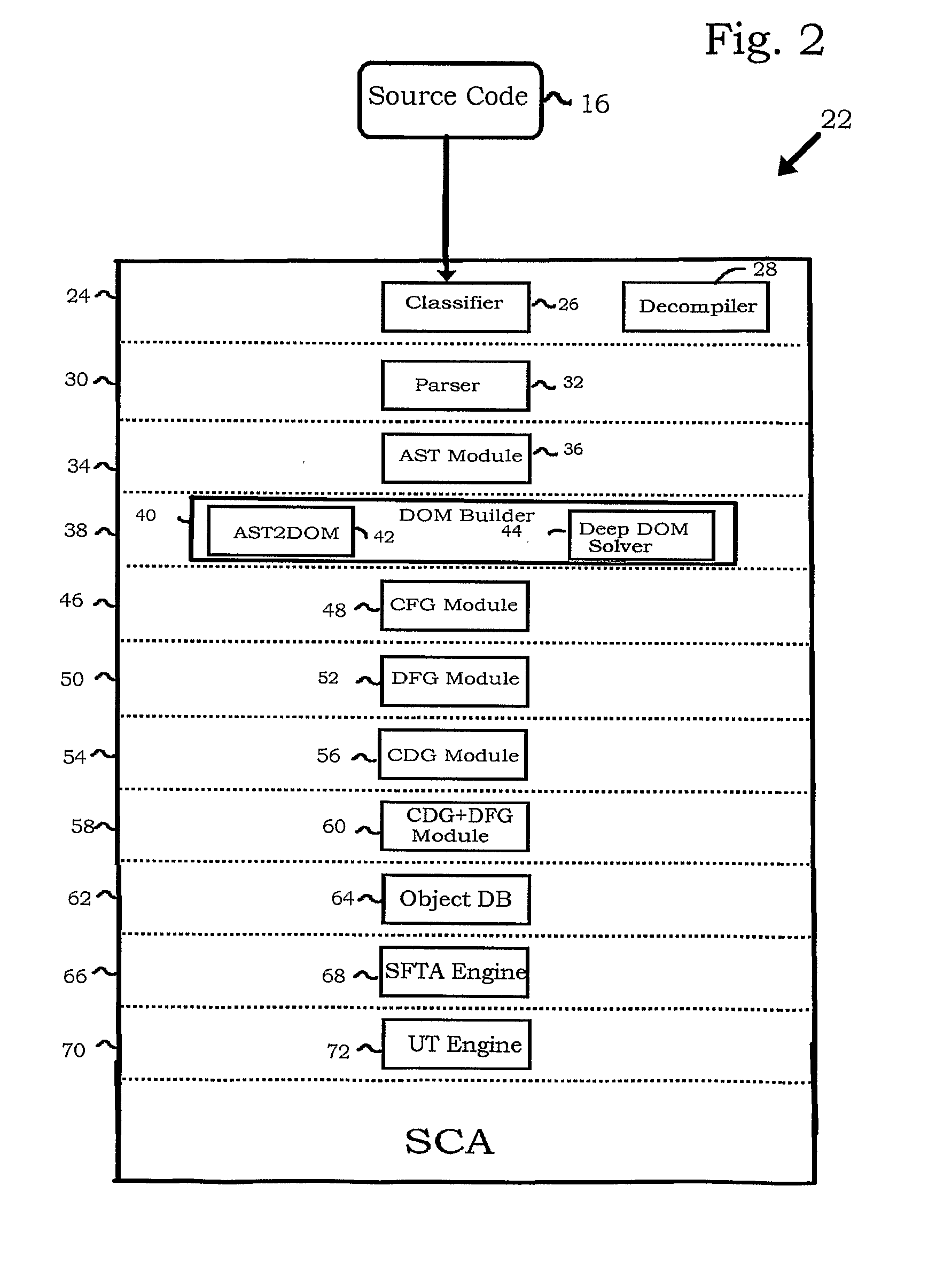
[0096]Referring again to FIG. 2, data flow graphs are constructed in layer 50, using DFG module 52. Reference is now made to FIG. 7, which is a data flow graph 112 that is constructed in accordance with a disclosed embodiment of the invention. A data flow graph describes data flow within a single method. Each time a value is assigned to a variable, the influencing object and the location of the assignment is recorded. As result, a graph can be constructed, in which the data flow nodes are variables in a specific location, and connections represent dependency...
example 3
[0110]Reference is now made to FIG. 9, which is a diagram illustrating construction of a data flow graph according to the method described with reference to FIG. 8, in accordance with a disclosed embodiment of the invention. As shown in the upper portion of FIG. 9, a data flow graph is constructed from a fragment of source code 142.
[0111]A control flow graph 144 and a duplicate control flow graph 146 are prepared, and the nodes of the latter assigned unique identifiers (1, 2, 3, 4). In the lower portion of the duplicate control flow graph 146 has been elaborated to illustrate that each of its nodes is associated with respective tables of variables—a column 148 of tables containing respective arrays “VariablesThisBlockDependsOn”, and a set of tables 150, each being offset according to the rank of its associated node in the duplicate control flow graph 146. For example node 152 has been assigned unique identifier “1”, and has been associated with tables 154, 156. It will be recalled t...
PUM
 Abstract
Description
Claims
Application Information
 - R&D
- Intellectual Property
- Life Sciences
- Materials
- Tech Scout
- Unparalleled Data Quality
- Higher Quality Content
- 60% Fewer Hallucinations
Browse by: Latest US Patents, China's latest patents, Technical Efficacy Thesaurus, Application Domain, Technology Topic, Popular Technical Reports.
© 2025 PatSnap. All rights reserved.Legal|Privacy policy|Modern Slavery Act Transparency Statement|Sitemap|About US| Contact US: help@patsnap.com


