Eureka AIR delivers breakthrough ideas for toughest innovation challenges, trusted by R&D personnel around the world.

Hydraulic control device for automatic transmission

Inactive Publication Date: 2010-04-01
AISIN AW CO LTD +1
View PDF12 Cites 17 Cited by
  • Summary
  • Abstract
  • Description
  • Claims
  • Application Information

AI Technical Summary

Benefits of technology

[0009]It is therefore an object of the present invention to provide a hydraulic control device for an automatic transmission that can switch a fail-safe traveling state and a fail-safe stopping state even after a failure occurs, and can enhance a limp-home function.
[0011]Thus, the first command system can control all the shift speeds in a normal state, and the second command system can switch the fail-safe traveling state and the fail-state stopping state when a failure occurs in the first command system. As a result, even when a failure occurs in the first command system, the forward traveling state and the neutral state can be switched by using the second command system, whereby the limp-home function can be enhanced.
[0013]Thus, since the second system switch valve is switched between the supply position and the cutoff position, based on the signal pressure of the second system solenoid valve, the primary pressure to the hydraulic servos can be reliably switched when a failure occurs in the first command system. That is, the fail-safe traveling state and the fail-safe stopping state can be reliably switched when a failure occurs in the first command system.
[0017]Thus, the distribution switch valve is structured so as to receive the signal pressure of the second system solenoid valve in the forward-travel engagement-pressure input oil chamber when the first command system has a failure. Thus, when the first command system has a failure, the distribution switch valve can be switched between the first position and the second position by the signal pressure of the second system solenoid valve. Thus, for example, even if a failure occurs in the first command system in the reverse travel range or the non-travel range, and the distribution switch valve is located at the first position, the distribution switch valve can be switched to the second position by the second command system. Thus, the limp-home function can be enhanced.
[0019]Thus, the hydraulic control device includes, as the first system solenoid valve, the range setting solenoid valve that is driven by operation of the shift-range operating unit, and that sets the shift range inside the automatic transmission. That is, the shift range of the automatic transmission is switched by electric commands. Thus, since the hydraulic control device of the present invention is not configured so that the shift range is manually switched, shifting of the shift range becomes impossible when a failure occurs in the first command system. However, the fail-safe traveling state and the fail-safe stopping state can be switched by the second command system, whereby the limp-home function can be enhanced.

Problems solved by technology

However, if such a shift-by-wire system is used in the hydraulic control device which performs fail-safe operation by reverse input of the linear solenoid valves, the solenoid valves cannot be driven, that is, a hydraulic pressure cannot be switched, especially after the all-solenoids-off failure occurs.
That is, the hydraulic pressure cannot be switched after the all-solenoids-off failure occurs.
As a result, the driver may not select forward traveling and neutral.

Method used


Image

  • Hydraulic control device for automatic transmission
  • Hydraulic control device for automatic transmission
  • Hydraulic control device for automatic transmission

Examples


Embodiment Construction

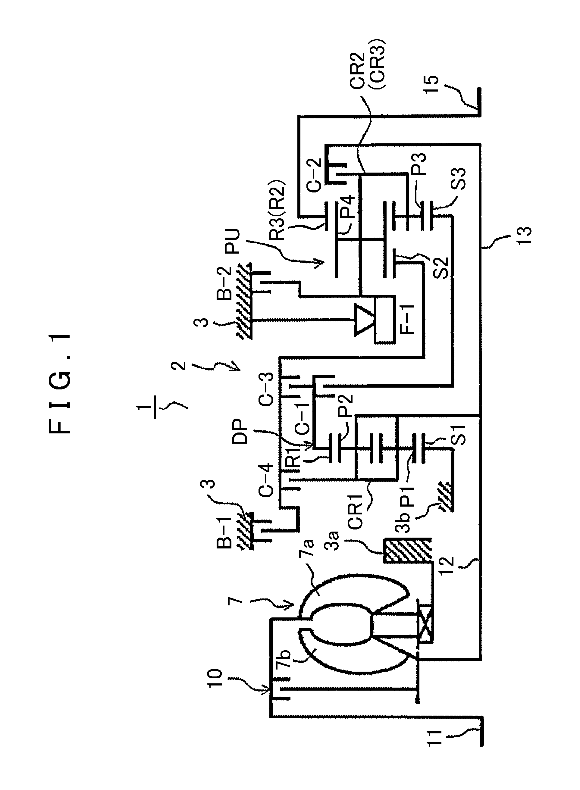
[0029]Hereinafter, an embodiment of the present invention will be described with reference to FIGS. 1 through 7B.

[0030][Structure of Automatic Transmission]

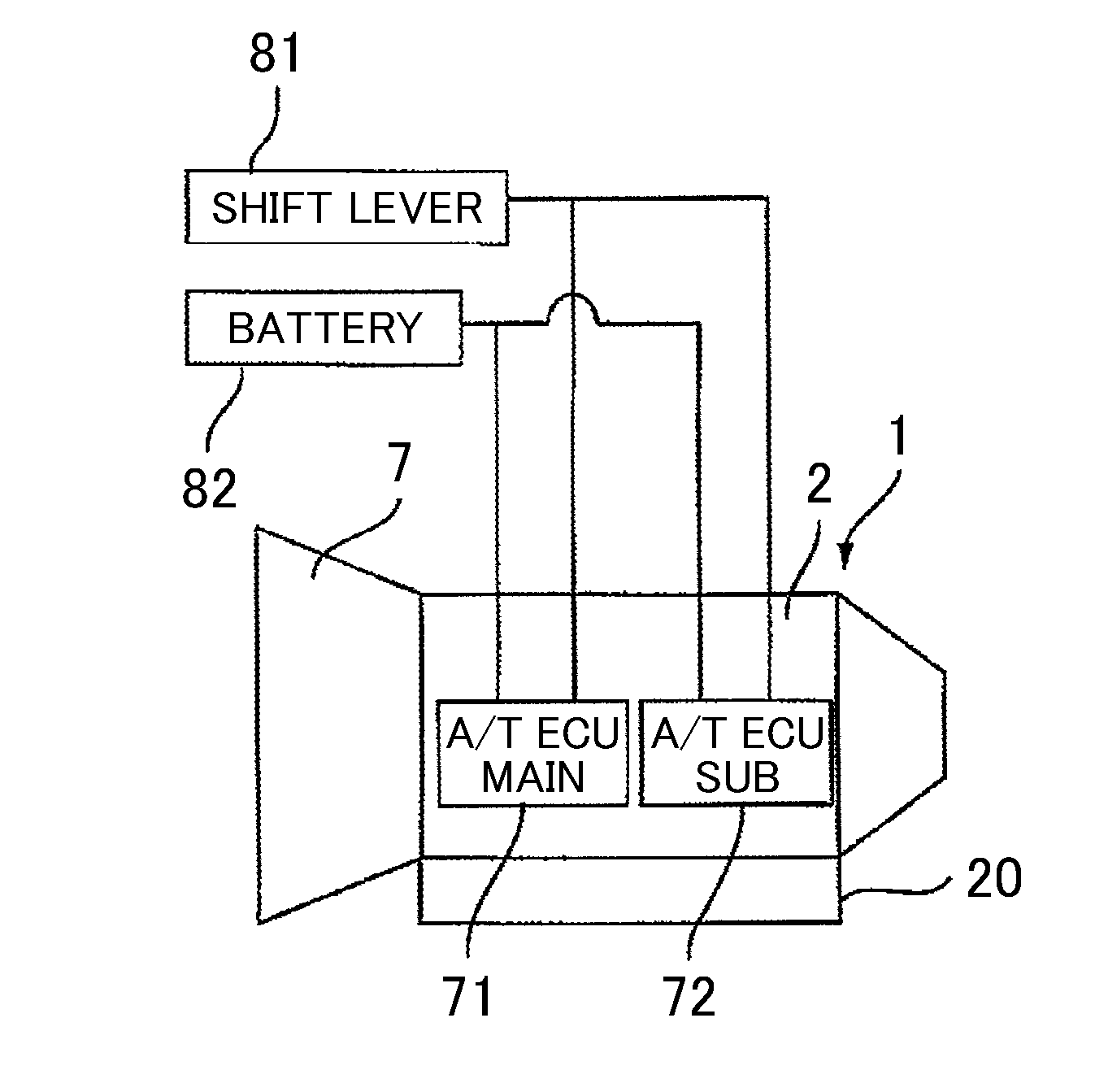
[0031]First, a schematic structure of a multi-stage automatic transmission (hereinafter simply referred to as an “automatic transmission”) to which the present invention can be applied will be described with reference to FIG. 1. As shown in FIG. 1, an automatic transmission 1, which is preferably used in, for example, an FR (front engine, rear drive) type vehicle, has an input shaft 11 of the automatic transmission 1 which connects to an engine (not shown), and includes a torque converter 7 and a speed change mechanism 2, which are disposed about the axial direction of the input shaft 11.

[0032]The torque converter 7 has a pump impeller 7a which is connected to the input shaft 11 of the automatic transmission 1, and a turbine runner 7b to which rotation of the pump impeller 7a is transmitted via a working fluid. The turbine runner...


PUM


Abstract

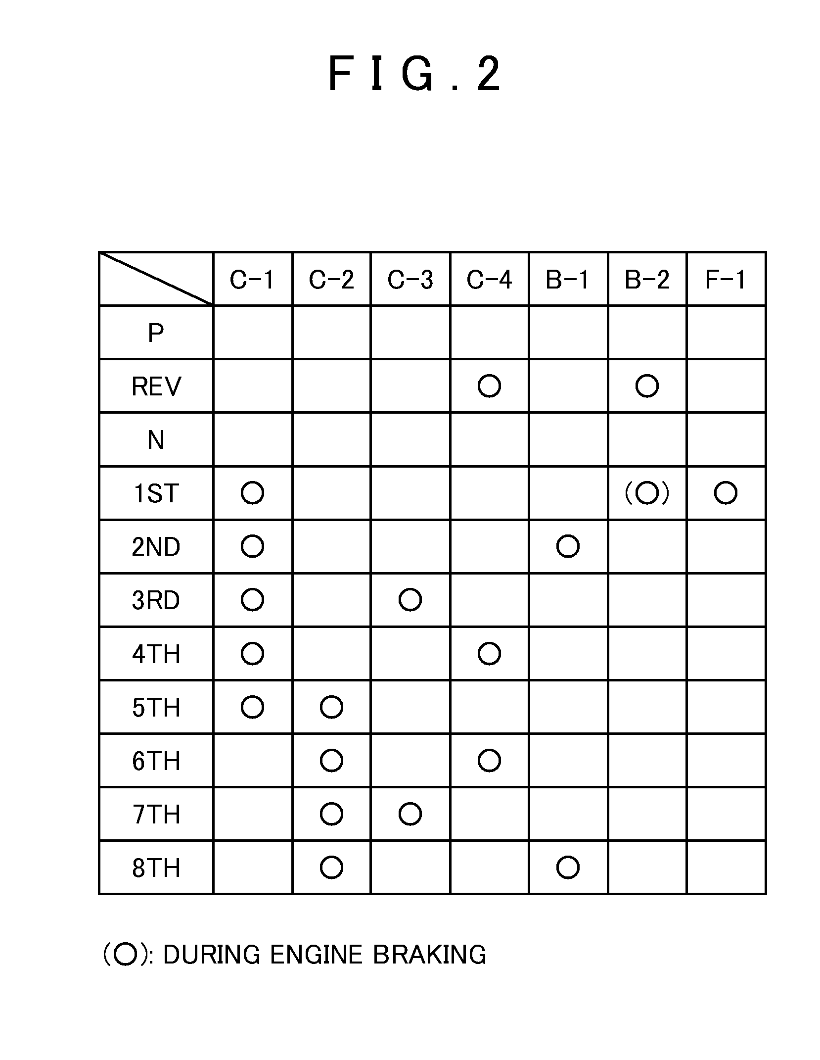
A hydraulic control device for an automatic transmission that includes a fail-safe function to establish a fail-safe traveling state where a predetermined shift speed is established, and a fail-safe stopping state where the primary pressure to all of the hydraulic servos is cut-off when a failure occurs. The hydraulic control device is able to switch between the fail-safe traveling state and the fail-safe stopping state even after a failure occurs, thereby enhancing a limp-mode function.

Description

INCORPORATION BY REFERENCE[0001]The disclosure of Japanese Patent Application No. 2008-255841 filed on Sep. 30, 2008 including the specification, drawings and abstract is incorporated herein by reference in its entirety.BACKGROUND OF THE INVENTION[0002]The present invention generally relates to a hydraulic control device for an automatic transmission mounted on, for example, a vehicle. More particularly, the present invention relates to a hydraulic control device for an automatic transmission which has a fail-safe function to establish a fail-safe traveling state where a predetermined shift speed is established, and a fail-safe stopping state where the primary pressure to all of the hydraulic servos is cut off, when a failure occurs due to, for example, computer failure, wire disconnection, or the like.DESCRIPTION OF THE RELATED ART [0003]With recent improvement in output performance of a linear solenoid valve, a hydraulic control device of an automatic transmission has been structu...

Claims


Application Information

Patent Timeline
IPC IPC(8): F16H61/18G06F19/00F16H59/68F16H61/12F16H61/68F16H61/684
CPCF16H61/0206F16H61/12F16H61/686Y10T477/6934F16H2061/1268F16H63/3483F16H2061/122
Inventor YOSHIOKA, YUHEINODA, KAZUYUKIITAZU, NAOKINOZAKI, YOSHINOBU
Owner AISIN AW CO LTD
Why Eureka
Eureka Blog
Learn More