Eureka AIR delivers breakthrough ideas for toughest innovation challenges, trusted by R&D personnel around the world.

Developing roller, developing roller production method, process cartridge, and electrophotographic apparatus

Active Publication Date: 2010-04-01
CANON KK
View PDF13 Cites 24 Cited by
  • Summary
  • Abstract
  • Description
  • Claims
  • Application Information

AI Technical Summary

Benefits of technology

[0008]1. Frictional chargeability of toner does not easily become excessive in a low-temperature low-humidity environment.
[0010]The present invention is directed to provide a developing roller which includes a surface layer satisfying the above-described requirements 1 and 2 at a high level, and a method for producing the developing roller. Further, the present invention is directed to provide an electrophotographic apparatus and a process cartridge which can stably provide a high-quality electrophotographic image.
[0015]According to the present invention, a developing roller can be provided which has a surface layer capable of achieving the compatibility between the inhibition of the occurrence of permanent compression set in a high-temperature high-humidity environment and the inhibition of excessive frictional charging of the toner in a low-temperature low-humidity environment. Further, according to the present invention, an electrophotographic apparatus and a process cartridge can be provided which stably produce a high-quality electrophotographic image.

Problems solved by technology

However, since such a surface layer is easily made flexible, the surface layer may be permanently deformed when a developing roller including such a surface layer abuts the photosensitive member in a static state for a long time period in a high-temperature high-humidity environment.

Method used

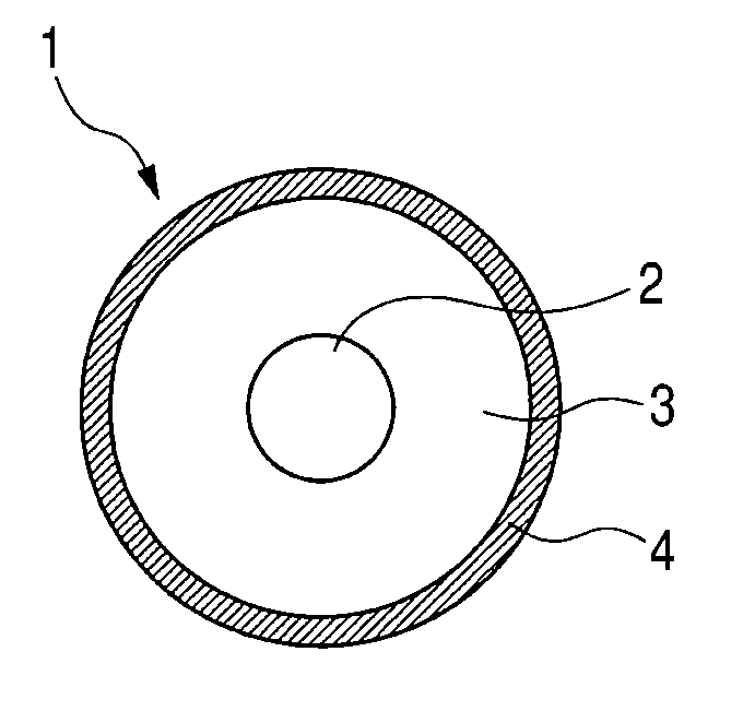
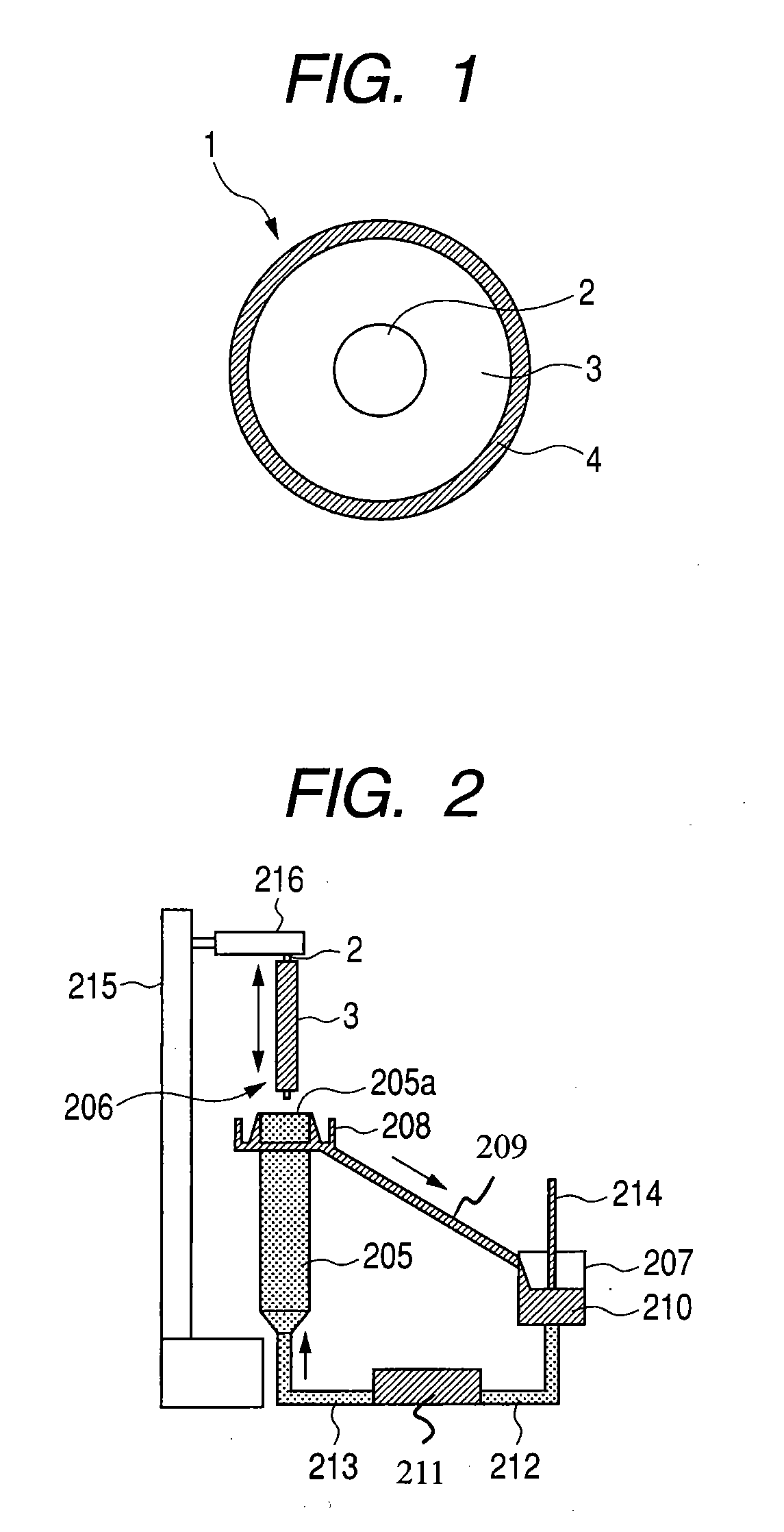
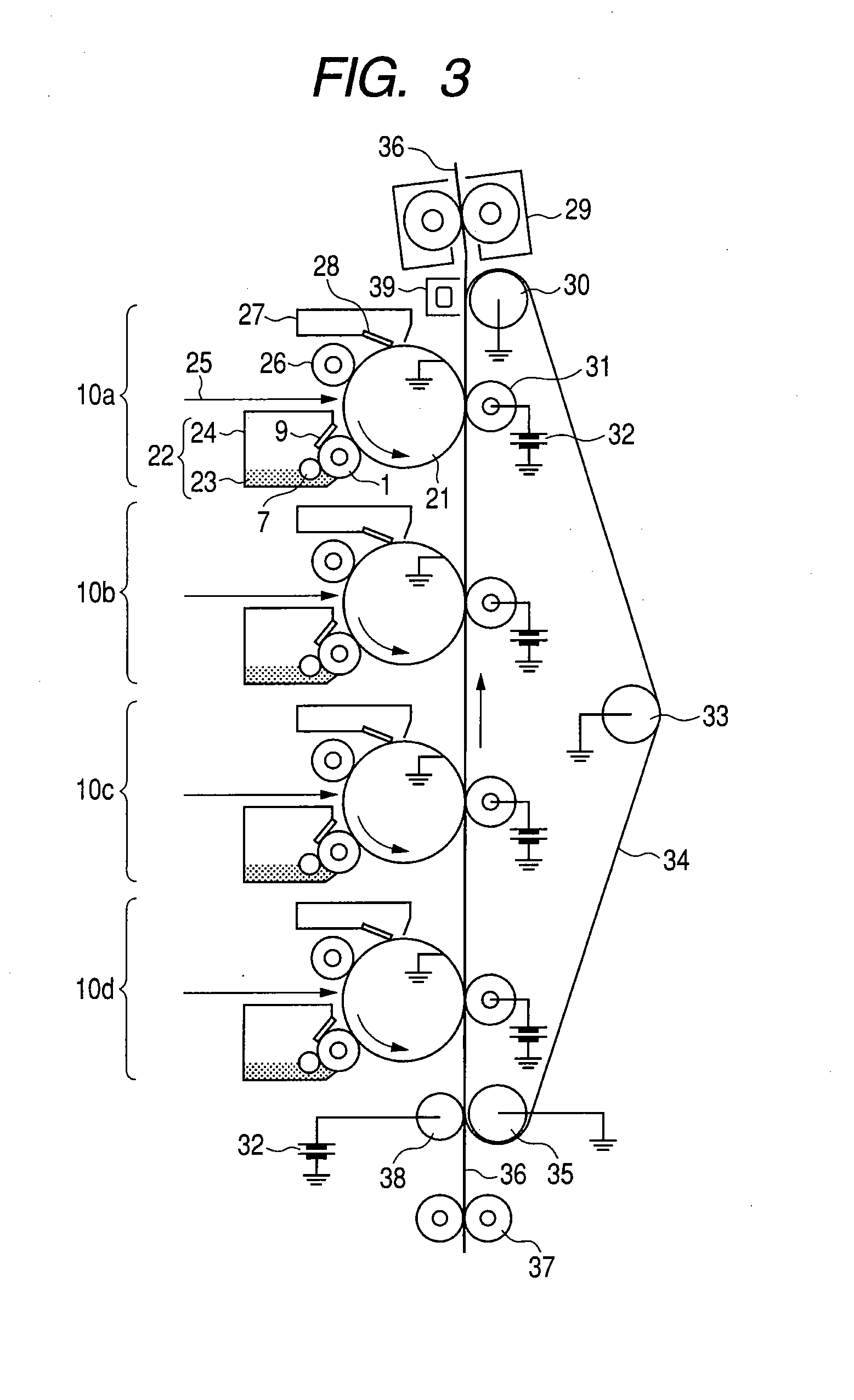

Image

  • Developing roller, developing roller production method, process cartridge, and electrophotographic apparatus
  • Developing roller, developing roller production method, process cartridge, and electrophotographic apparatus
  • Developing roller, developing roller production method, process cartridge, and electrophotographic apparatus

Examples


example 1

[0293]The coating solution (1) for surface layer formation, which was kept at a liquid temperature of 23° C., was poured into a cylinder with an inner diameter of 32 mm and a length of 300 mm from its bottom at a rate of 250 cc per minute. Coating solution which flowed out from the upper end of the cylinder was re-circulated into the cylinder from the bottom. The produced mandrel with a resin layer formed thereon was dipped in the cylinder at a dipping rate of 100 mm / s, was then stopped for 10 seconds, and thereafter drawn up at an initial rate of 300 mm / s and a final rate of 200 mm / s, followed by natural drying for 60 minutes. Next, the coating film formed on the periphery of the resin layer was subjected to heat treatment at 140° C. for 2 hours and was cured, to produce the developing roller (1) in Example 1 having a surface layer with a thickness of 10 μm.

example 2 to example 10

[0294]The developing roller in each of the Examples was produced in the same manner as in Example 1, except that the coating solutions (2) to (10) for surface layer formation were used instead of the coating solution (1) for surface layer formation. The results are shown in Table 2.

example 11

[0295]The developing roller (11) in Example 11 having a 3 μm-thick resin layer was produced in the same manner as in Example 1, except that the coating solution (11) for surface layer formation was used instead of the coating solution (1) for surface layer formation. The results are shown in Table 2.


PUM

PropertyMeasurementUnit
Percent by massaaaaaaaaaa

Abstract

A developing roller is provided which supplies a toner to a photosensitive member to develop an electrostatic latent image formed on the photosensitive member. The developing roller has a surface layer which includes carbon black and a polyurethane resin. The polyurethane resin has a specific structure. The surface layer has a specific ester group concentration and a specific urethane group concentration.

Description

BACKGROUND OF THE INVENTION[0001]1. Field of the Invention[0002]The present invention relates to a developing roller, and a method for producing a developing roller used in contact with a photosensitive member set in an electrophotographic apparatus such as a receiving apparatus of a copying machine, a printer and a facsimile. Further, the present invention relates to a process cartridge and electrophotographic apparatus which use this developing roller.[0003]2. Description of the Related Art[0004]Japanese Patent Application Laid-Open Nos. H9-12192 and H8-208087 disclose a developing roller used in an electrophotographic apparatus which has a mandrel and an elastic layer including polyurethane obtained by reacting a polyol and a polyisocyanate on the periphery of the core shaft.[0005]Developing rollers are required to have as a basic function a function of frictionally charging toner to a suitable level. However, in a low-temperature low-humidity environment, for example, in an envi...

Claims


Application Information

Patent Timeline
IPC IPC(8): G03G21/16G03G15/08G03G5/00
CPCG03G15/0818Y10T29/49544Y10T29/4956Y10T29/49563G03G15/0808G03G2215/0861G03G2215/0863
Inventor KURACHI, MASAHIROYAMADA, MASAKISAKURAI, YUJINAKAMURA, MINORU
Owner CANON KK
Why Eureka
Eureka Blog
Learn More