
Radiation image diagnosing system

a radiation image and diagnostic system technology, applied in the field of radiation image diagnostic system, can solve the problems of difficult to diagnose the reconstructed radiation image efficiently, and achieve the effect of efficient diagnosis

Inactive Publication Date: 2010-04-01
FUJIFILM CORP
View PDF9 Cites 6 Cited by
  • Summary
  • Abstract
  • Description
  • Claims
  • Application Information

AI Technical Summary

Benefits of technology

[0009]It is an object of the present invention to provide a radiation image diagnosing system which allows for efficient diagnoses.
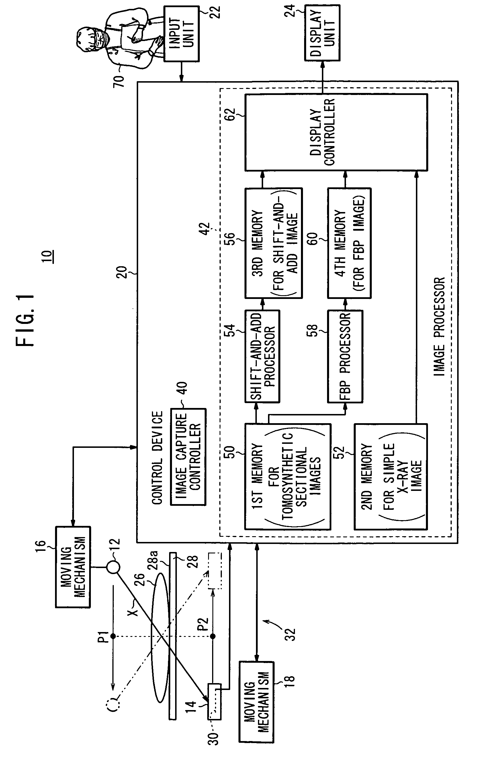
[0011]With the above arrangement, the shift-and-add image and the FBP image are displayed parallel to each other on the display unit. Since the doctor who uses the radiation image diagnosing system can view both the shift-and-add image and the FBP image at one time, the doctor can diagnose the subject efficiently.
[0013]Therefore, the simple X-ray image and at least one of the shift-and-add image and the FBP image can be displayed parallel to each other on the display unit. As the doctor can view the simple X-ray image and at least one of the shift-and-add image and the FBP image, the doctor can diagnose the subject efficiently.
[0015]Consequently, the shift-and-add image or the FBP image can be displayed in the area of interest within the displayed simple X-ray image. Therefore, the shift-and-add image or the FBP image can be displayed in the area of interest against the background of the displayed simple X-ray image. As a result, the doctor can diagnose the subject with increased convenience.
[0018]When the display controller enlarges or reduces one of the shift-and-add image and the FBP image or changes a display range of the one of the shift-and-add image and the FBP image, the display controller may also enlarge or reduce the other of the shift-and-add image and the FBP image or change a display range of the other of the shift-and-add image and the FBP image. Since the radiation image diagnosing system can display the shift-and-add image and the FBP image in relation with each other, the doctor can easily compare the shift-and-add image and the FBP image with each other. Therefore, the doctor can diagnose the subject more efficiently.

Problems solved by technology

Since doctors who are handling reconstructed radiation images are uncertain about which one of the reconstructing processes produces better reconstructed radiation images, they find it difficult to diagnose the reconstructed radiation images efficiently.

Method used


Image

  • Radiation image diagnosing system
  • Radiation image diagnosing system
  • Radiation image diagnosing system

Examples


embodiment

A. Embodiment

1. Configuration of Radiation Image Diagnosing System 10

[0025]FIG. 1 shows in block form a radiation image diagnosing system 10 according to an embodiment of the present invention.

[0026]As shown in FIG. 1, the radiation image diagnosing system 10 comprises a radiation source 12, a cassette 14, a first moving mechanism 16, a second moving mechanism 18, a control device 20, an input unit 22, and a display unit 24.

[0027]The radiation source 12 emits a radiation X at a prescribed dosage in response to a command from the control device 20. The cassette 14 houses a radiation conversion panel 30 therein. The radiation conversion panel 30 detects the radiation X that has been emitted from the radiation source 12 and passed through a subject 26 (patient) lying on a support surface 28a of an image capturing base 28, and converts the detected radiation X into radiation image information. The radiation conversion panel 30 outputs the converted radiation image information to the con...


PUM


Abstract

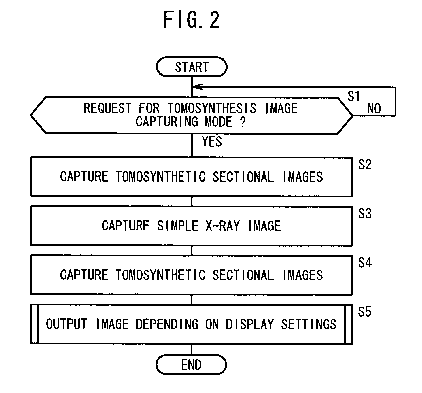
A radiation image diagnosing system includes a tomosynthesis image capturing assembly for acquiring the data of a plurality of tomosynthetic sectional images. The acquired data of the tomosynthetic sectional images are processed to reconstruct a shift-and-add image by a shift-and-add processor. The acquired data of the tomosynthetic sectional images are also processed to reconstruct an FBP image by an FBP processor. The shift-and-add image and the FBP image are displayed parallel to each other on a display unit.

Description

CROSS-REFERENCE TO RELATED APPLICATIONS[0001]This application is based upon and claims the benefit of priority from Japanese Patent Application No. 2008-254256 filed on Sep. 30, 2008 and Japanese Patent Application No. 2009-187695 filed on Aug. 13, 2009 in the Japanese Patent Office, of which the contents are incorporated herein by reference.BACKGROUND OF THE INVENTION[0002]1. Field of the Invention[0003]The present invention relates to a radiation image diagnosing system including a tomosynthesis image capturing assembly, and more particularly to a radiation image diagnosing system which is capable of displaying parallel sectional images that have been reconstructed according to different processes from a plurality of sectional images acquired by a tomosynthesis image capturing assembly.[0004]2. Description of the Related Art[0005]Tomosynthesis is known in the art as a process of capturing sectional radiation images. According to tomosynthesis, a radiation is applied from a radiati...

Claims


Application Information

Patent Timeline
IPC IPC(8): G06K9/00
CPCG06T11/005G06T2211/436G06T2211/421
Inventor NISHIMURA, TOMOYOSHIENOMOTO, JUNSAWADA, HIROFUMIAKAHORI, SADATOKANAGAWA, EIICHIOHTA, YASUNORIIDA, NORIAKI
Owner FUJIFILM CORP
Learn More