
Vehicle door mirror mount structure

Inactive Publication Date: 2010-03-18
HONDA MOTOR CO LTD
View PDF14 Cites 12 Cited by
  • Summary
  • Abstract
  • Description
  • Claims
  • Application Information

AI Technical Summary

Benefits of technology

[0008]An object of the invention is to provide a mount structure of a vehicle door mirror which may provide occupants with a wider vision.

Problems solved by technology

In this structure, the door mirror mounting unit and a mirror base may disadvantageously hinder occupants' visibility outside of the vehicle.

Method used


Image

  • Vehicle door mirror mount structure
  • Vehicle door mirror mount structure
  • Vehicle door mirror mount structure

Examples


Embodiment Construction

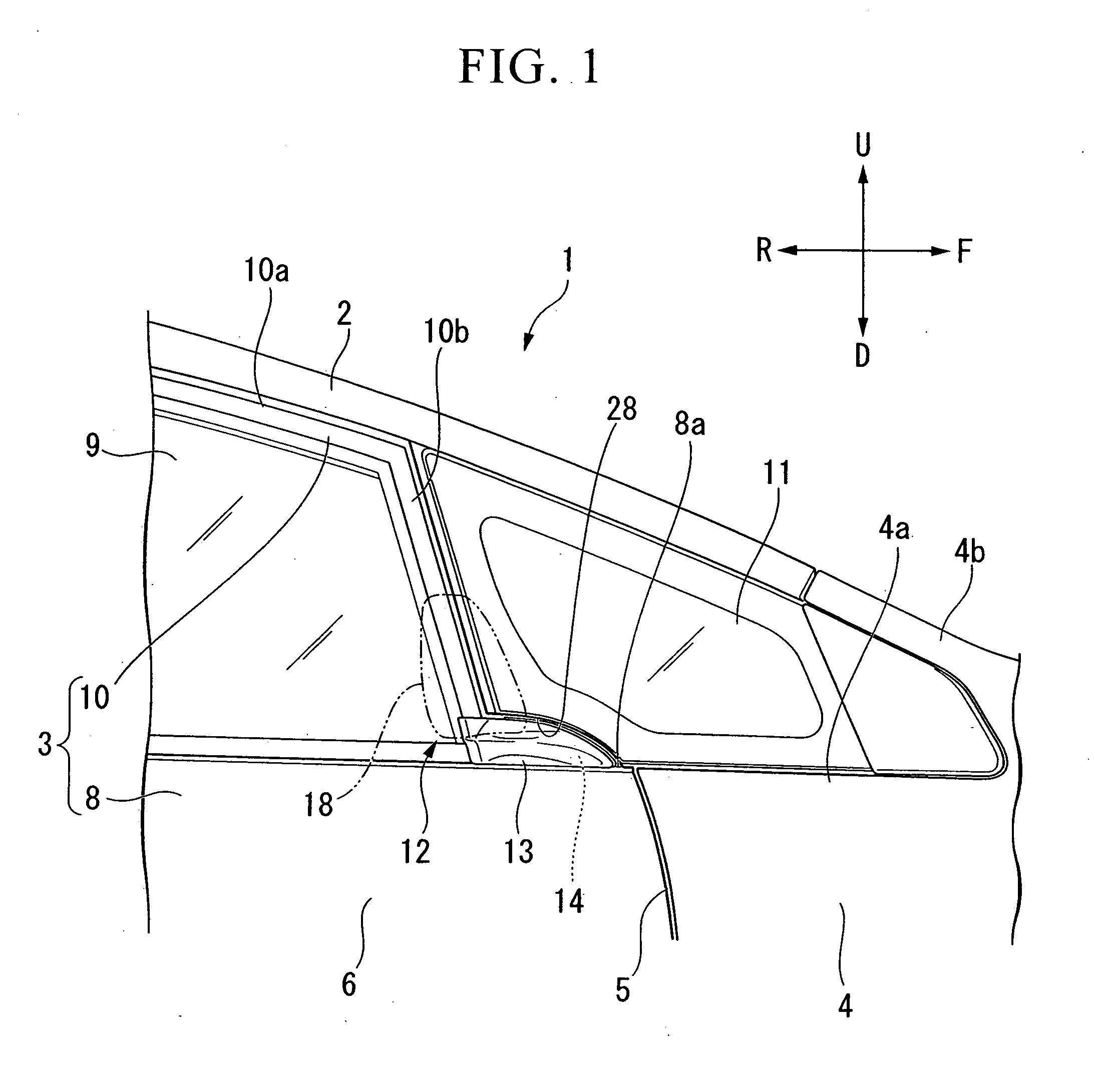
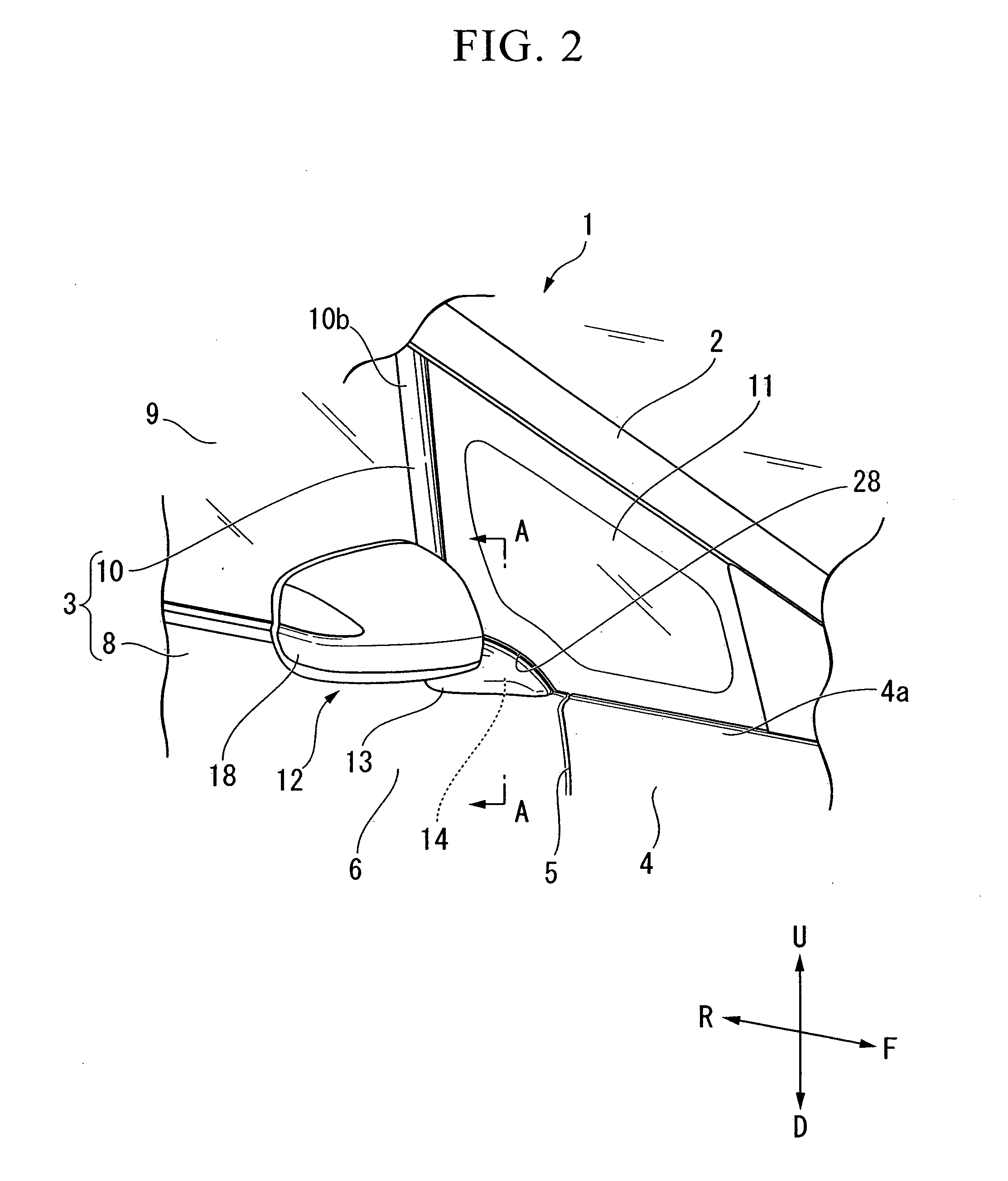
[0057]Referring now to the drawings, an embodiment of the invention will be described. In the following description, the terms “upper,”“lower,”“front” and “rear” correspond to directions of those members mounted on a vehicle body unless otherwise noted. Arrows U, D, O and I represent directions of upper, lower, outside and inside of the vehicle, respectively.

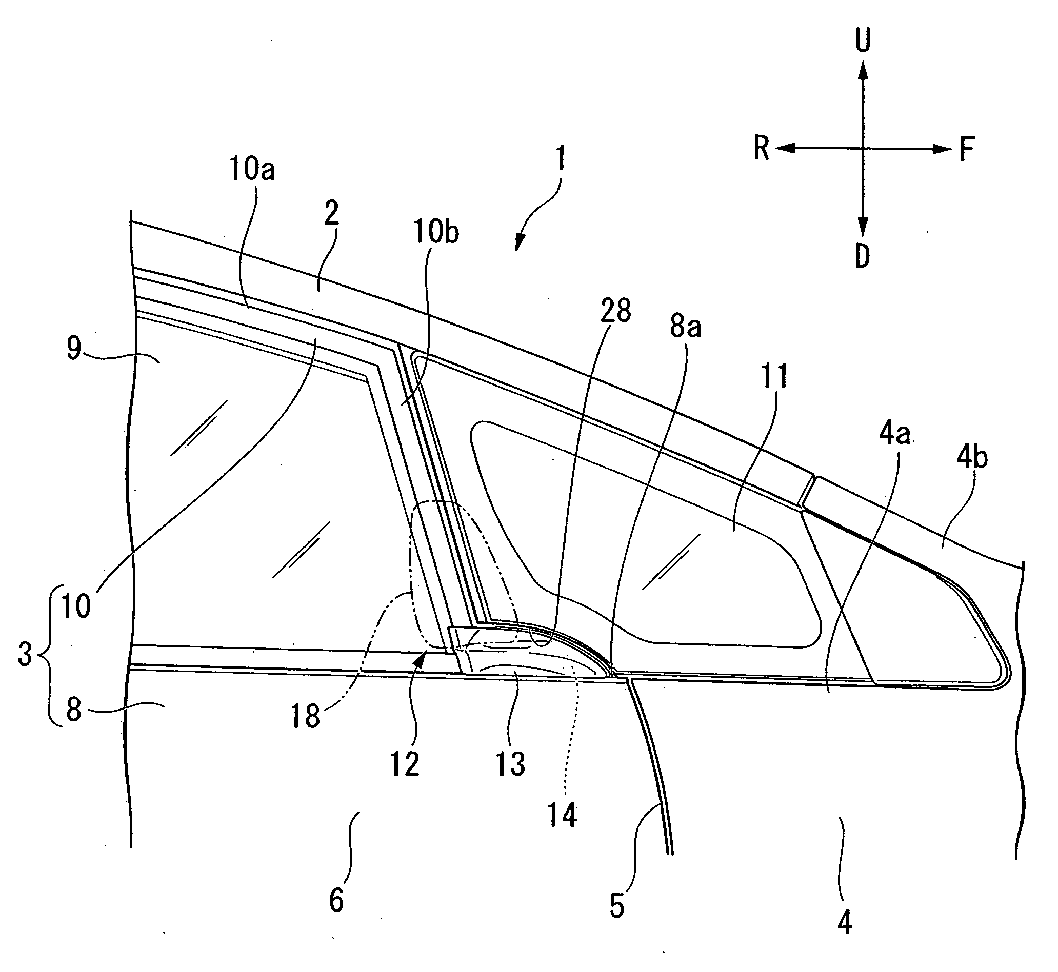
[0058]FIGS. 1 and 2 illustrate a vehicle 1 provided with a door mirror mounting structure according to the invention. In the drawings, a front pillar provided continuously to a vehicle roof is denoted by a reference numeral 2, a side door is denoted by 3 and a body side panel is denoted by 4. The body side panel 4 forms a part of a periphery 5 of a side door opening.

[0059]FIG. 3 shows a cross section taken along line A-A in FIG. 2. FIG. 4 is an exploded view of a front portion of the side door 3.

[0060]The side door 3 includes a door body 8 and a door sash 10. The door body 8 includes an outer panel which forms a side surface of ...


PUM


Abstract

A mount structure of a vehicle door mirror on a side door, the side door including: a door body having an outer panel and an inner panel which are joined together; and a door sash provided at an upper part of the door body so as to form an outer frame of the door body, wherein a door mirror mounting unit which mounts the door mirror is provided at an upper edge of the door body and at a vehicle front side of the door sash.

Description

BACKGROUND OF THE INVENTION[0001]1. Field of the Invention[0002]The present invention relates to a mount structure of a door mirror to a vehicle side door.[0003]Priority is claimed on Japanese Patent Application No. 2007-269062 filed Oct. 16, 2007, the content of which are incorporated herein by reference.[0004]2. Background Art[0005]Some vehicles have a substantially triangular-shaped front corner window at a front side of a front pillar to give occupants front, left and right views. Such a front corner window is fixed to a vehicle body.[0006]A known mount structure of a vehicle door mirror includes a door mirror mounting unit attached to a front edge, which is formed wider, of a side door sash (see Japanese Unexamined Patent Application, First Publication No. 2004-217033).[0007]The door mirror mounting unit of such a door mirror mounting structure is provided along the door sash at the front side of the vehicle. In this structure, the door mirror mounting unit and a mirror base ma...

Claims


Application Information

Patent Timeline
IPC IPC(8): B60R1/06B60J5/04
CPCB60R1/06B60J5/0404
Inventor OHE, TOMOHIRO
Owner HONDA MOTOR CO LTD
Learn More