Colour conversion for a multy-primary display

Inactive Publication Date: 2010-03-11
KONINKLIJKE PHILIPS ELECTRONICS NV
View PDF6 Cites 2 Cited by
  • Summary
  • Abstract
  • Description
  • Claims
  • Application Information

AI Technical Summary

Benefits of technology

[0015]The algorithm requires a relatively low computationally effort because the position of the input pixel vector with respect to the boundaries is simple to determine. For example, in a luminance / chrominance space the boundaries are made up out of straight lines and only the equations of these straight lines have to be known. Consequently, it is relatively easy to determine the interpolation factor. Further, because the display drive vector is determined from boundary display vectors which end on the boundaries it is relatively easy to perform the interpolation. The algorithm optimizes the performance if the boundary vectors on the boundaries nearest to the input vector are selected to determine the interpolation factor. This selection of the boundary vectors leads to a minimal flicker, color breakup, or pixel pattern visibility. As will become clear from the description of the embodiments, many alternatives exist to perform the algorithm.
[0020]The selection of the two boundary vectors on the boundaries of the two gamuts nearest to the input pixel vector may be performed by transforming the three display boundary vectors in the display color space to three boundary vectors in the linear color space. The boundary luminances of these three boundary vectors in the linear color space is calculated. The boundary luminances in the linear color space are compared with an input luminance of the input vector in the linear color space. The two display boundary vectors of the three display boundary vectors are selected which have the boundary luminance nearest to the input luminance such that the input color vector is in-between the selected boundary vectors. The interpolation factor is determined from the position of the input pixel vector with respect to the two boundary vectors in the linear color space with the two boundary luminances nearest to the input luminance. This approach has the advantage that no real time transformations from the display color primaries in the display color space to the linear color space are required. Further, the determination of the nearest boundary vectors in the linear color space and in the display color space is quite simple because the position of the boundary vectors in the display color space is already pre-selected and stored, for example in a look up table. Consequently, only the luminances in the linear color space need to be determined to be able to select the two nearest boundary vectors to be used for the determination of the interpolation factor. It has to be noted that the determination of the interpolation factor in the linear color space and the subsequent interpolation in the display color space becomes very simple if a linear interpolation is used and the input vector and the boundary vectors end on a same straight line.
[0025]In an embodiment the interpolation is a linear interpolation. In such a linear interpolation it suffices to have two display drive vectors which end at the nearest boundaries and which together with the to be interpolated value of the display drive vector corresponding to the input drive vector end on a same straight line. Now, the determination of the interpolation factor and the interpolation itself are very simple. In an embodiment wherein this line runs through the origin of the color space, for example the luminance / chrominance space, the algorithm becomes especially simple. It has to be noted that the display drive vectors comprise sub-drive vectors, one for each one of the m groups of display primaries. These sub-drive vectors are the actually used drive values for the display primaries of the each one of the m groups. The total color displayed by pixel composed out of the m groups of sub-pixels is represented by the display drive vector.

Problems solved by technology

Although this prior art provides a high performance, it does not disclose how to efficiently determine the drive values of the sub-pixels during the subfields.

Method used


Image

  • Colour conversion for a multy-primary display
  • Colour conversion for a multy-primary display
  • Colour conversion for a multy-primary display

Examples


Embodiment Construction

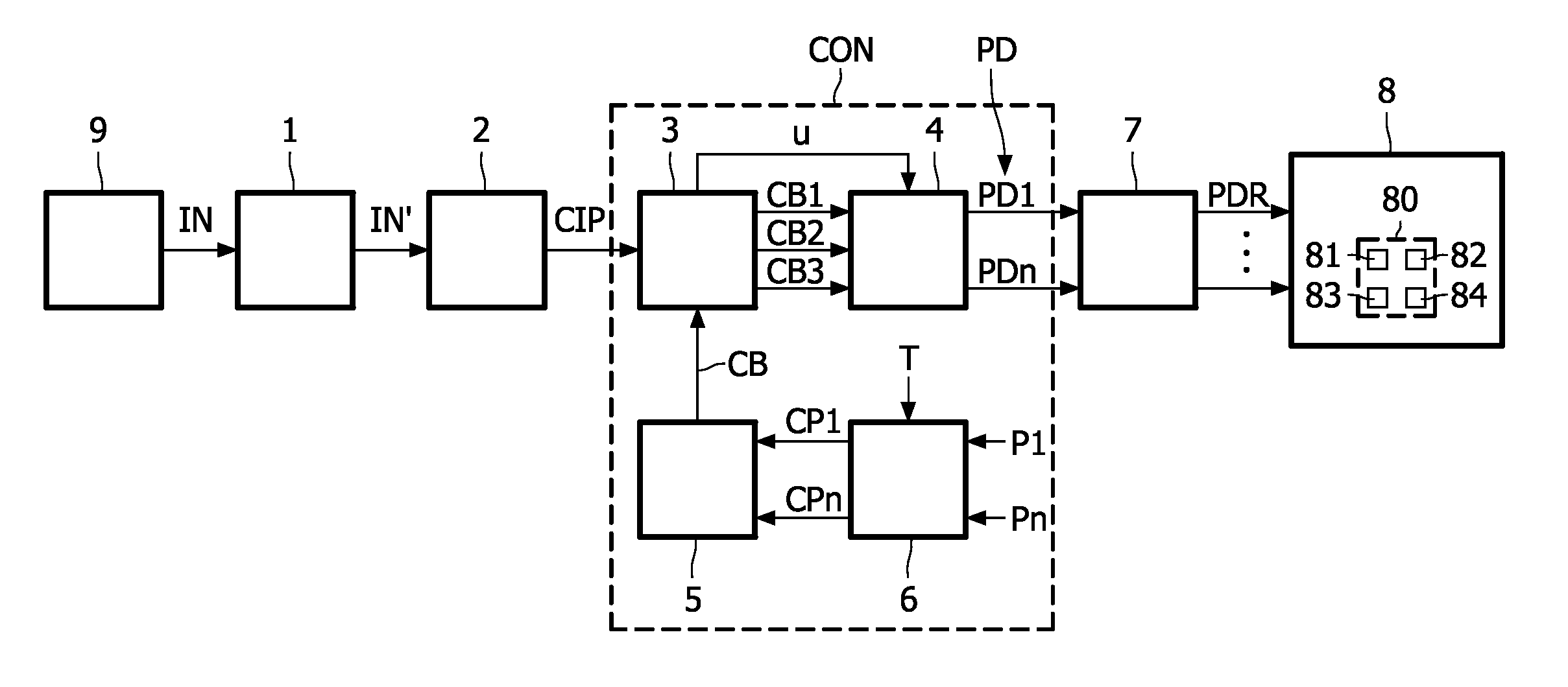
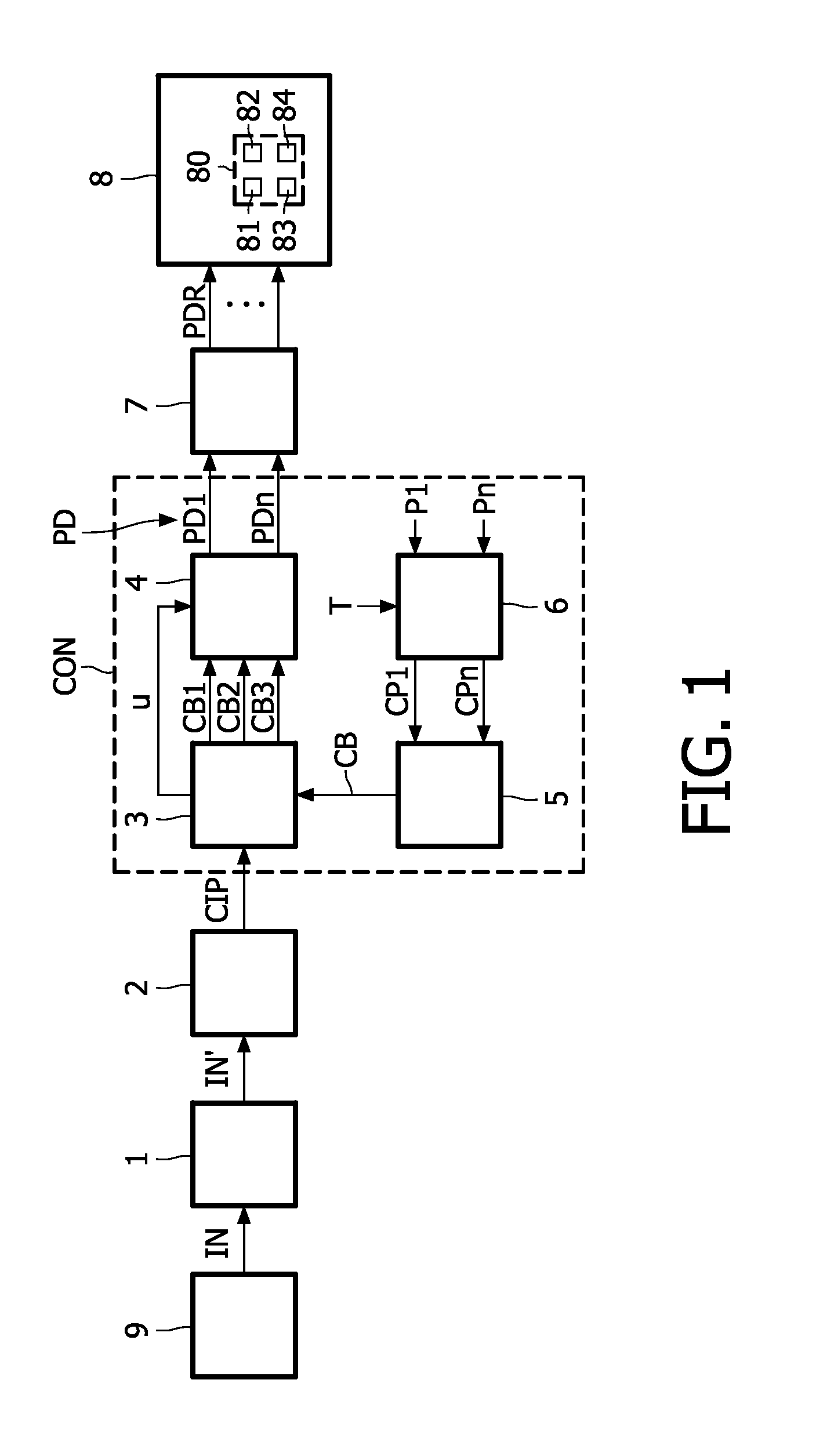
[0037]FIG. 1 shows a block diagram of a display apparatus with circuit for performing a multi-primary conversion in accordance with an embodiment of the invention. The circuit CON which performs the multi-primary conversion comprises a boundary vector determining circuit 3, an interpolating circuit 4, a transforming circuit 6, and a boundary constructing circuit 5. The display apparatus comprises an optional transforming circuit 2, a drive circuit 7, and a display device 8.

[0038]The source gamma operation is performed by the optional block 1 which receives an input signal IN, for example from a camera 9 and supplies a signal IN′ which has been gamma pre-corrected. If the input signal is gamma pre-corrected, or is not defined in a linear color space due to another reason, the optional transforming block 2 transforms the signal IN′ from the non-linear color space to a linear color space to obtain the input signal CIP for the multi-primary converter CON. If the signal inputted to the m...


PUM


Abstract

A multi-primary conversion method for converting (CON) an input vector (CIP) defining a color of an input pixel in a linear color space (X, Y, Z) into a drive vector (PD) having n components for driving n display primaries (P1, . . . , Pn) of a display color space. The drive vector (PD) comprises m sub-drive vectors (PDi) for driving m groups of the display primaries (P1, . . . , Pn). The conversion method comprises: determining (5, 6; 9, 10) in the linear color space (X, Y, Z) a position of the input vector (CIP) with respect to boundaries (CB) of at least two of three gamuts (FG, ELG, ELCG) being defined by transformed display primaries (CP1, . . . , CPn), wherein the three gamuts (FG, ELG, ELCG) indicate: a full gamut (FG) comprising all colors being reproducible with the m groups of the sub-drive vectors (PDi), an equal luminance sub-gamut (ELG) comprising all colors having equal luminance and being reproducible with each one of the m groups of the sub-drive vectors (PDi), and an equal luminance and equal chrominance sub-gamut (ELCG) comprising all colors being reproducible with each one of the m groups of sub-drive vectors (PDi) each having equal luminance and equal chrominance. Selecting (3; 12, 13) two boundary vectors (CB 1, CB2) on the boundaries (CB) of the three gamuts (FG, ELG, ELCG) to enable the input vector (CIP) to be interpolated from the two boundary vectors (CB1, CB2). Determining (3; 14) an interpolation factor (u) from the position of the input vector (CIP) with respect to the selected two boundary vectors (CB1, CB2). And, interpolating (4; 11) in the display color space the drive vector (PD) representing the color of the input vector (CIP) from the interpolation factor (u) and two boundary vectors (PB1, PB 2) in the display color space corresponding to the selected two boundary vectors (CB1, CB2) in the linear color space.

Description

FIELD OF THE INVENTION[0001]The invention relates to a multi-primary conversion method, a system for multi-primary conversion, a display device comprising the system for multi-primary conversion, a camera comprising the system for multi-primary conversion, and a computer program product.BACKGROUND OF THE INVENTION[0002]WO 2004 / 032523 A1 discloses a color display device which is provided with a plurality of picture elements. The display device has more than the usual three display primaries to be able to display a wider gamut of colors. Two selectable light sources have different predetermined radiance spectra. Color filters in combination with the selectable light sources are able to produce respective first and second primary colors on the display device. A controller selects alternatively one of the selectable light sources and provides a portion of the picture elements with image information corresponding to the respective primary colors obtainable with the selected light source....

Claims


Application Information

Patent Timeline
IPC IPC(8): G09G5/02
CPCG09G5/02G09G2300/0452G09G2310/0235G09G2320/0242H04N19/426G09G2340/06H04N1/54H04N9/67G09G2320/0247
Inventor HEKSTRA, GERBEN JOHANBELIK, OLEG
Owner KONINKLIJKE PHILIPS ELECTRONICS NV
Why Eureka
Try Eureka