
Method for analyzing fault caused in virtualized environment, and management server

Inactive Publication Date: 2010-03-04
HITACHI LTD
View PDF11 Cites 41 Cited by
  • Summary
  • Abstract
  • Description
  • Claims
  • Application Information

AI Technical Summary

Benefits of technology

[0009]The present invention was conceived in view of the above problems and it is therefore the object of the present invention to provide a method for analyzing a fault in a virtualized environment and a management server that enable easy and quick identification of a location where a fault has been caused in a virtualized environment.
[0012]According to the present invention, easy and quick identification of a site where a fault has been caused in a virtualized environment can be carried out.

Problems solved by technology

However, it is not so easy to identify a site where a fault has been caused in an environment like that described above to which virtualization is applied.
This procedure requires a large amount of labor.
That is, these technologies cannot realize easy and quick identification of a cause of a fault and handling of the fault.

Method used


Image

  • Method for analyzing fault caused in virtualized environment, and management server
  • Method for analyzing fault caused in virtualized environment, and management server
  • Method for analyzing fault caused in virtualized environment, and management server

Examples


Embodiment Construction

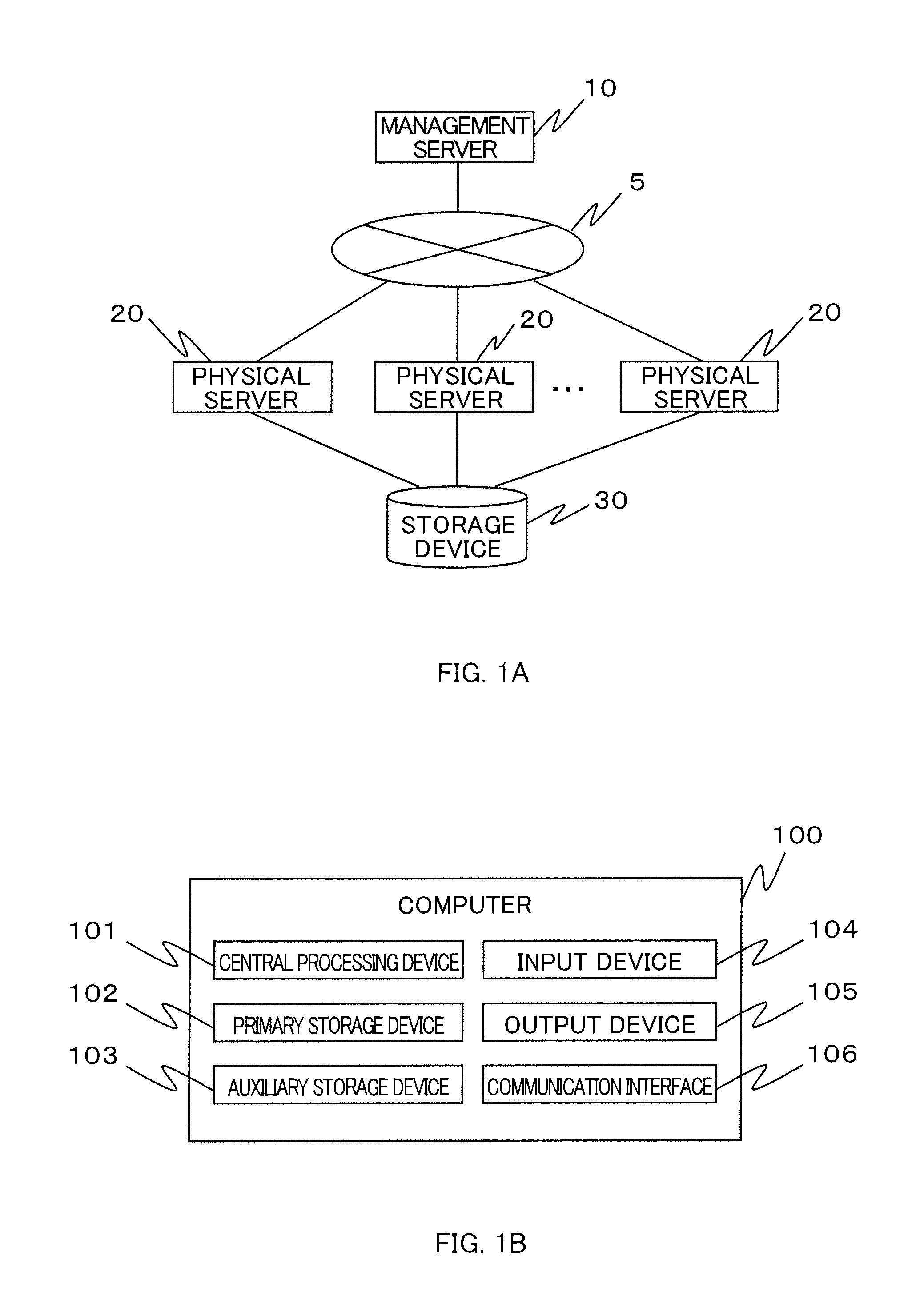
[0036]In FIG. 1A is shown a hardware environment adopted for implementing a virtualized system which is described as an embodiment. As shown therein, the hardware environment is configured to include a management server 10, one or more physical servers 20 communicatively connected with the management server 10 via a communication network 5 and monitored by the management server 10, and a storage device 30 accessible from the physical server 20.

[0037]The communication network 5 connecting the management server 10 with the physical server 20 is, for example, a LAN (Local Area Network). The physical server 20 and the storage device 30 are communicatively connected with each other through a LAN or a SAN (Storage Area Network). The storage device 30 is, for example, a disk array device or a NAS (Network Attached Storage).

[0038]The management server 10 and the physical server 20 may be computers (information processing apparatuses) such as a personal computer, or a blade installed in a bl...


PUM


Abstract

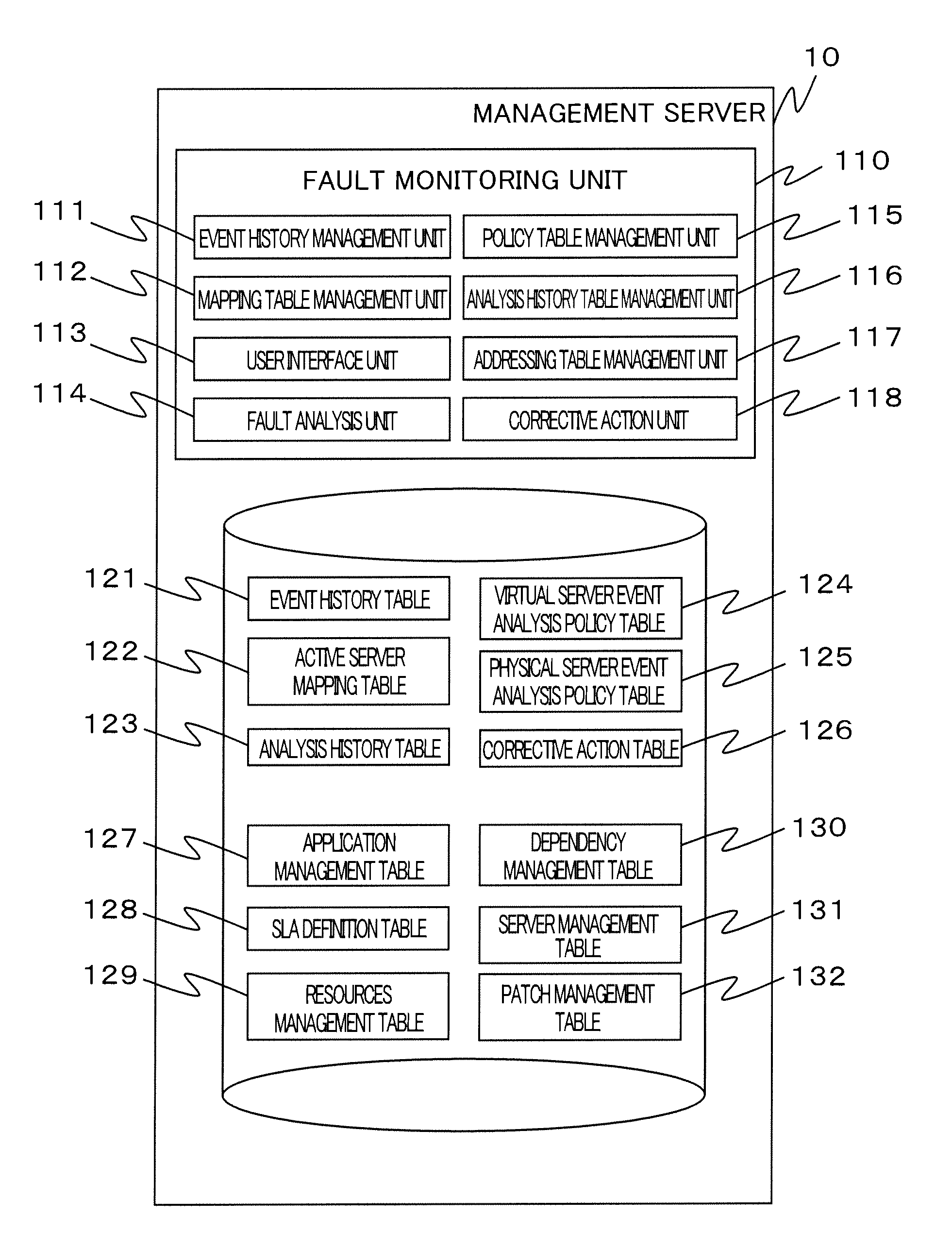
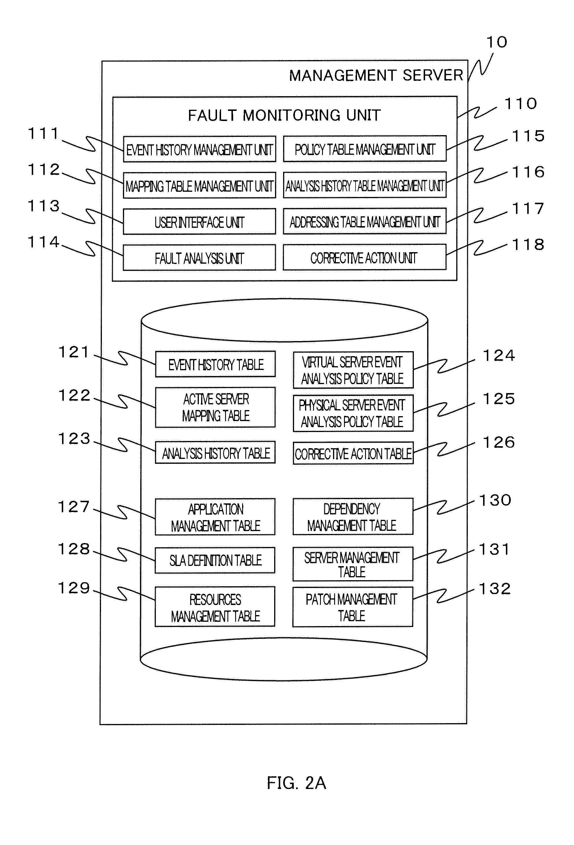
To enable easy and quick identification of the location of a fault in a virtualized environment, a physical server 20 is communicatively connected with a management server 10 accumulating and storing a first event history of a history of events having occurred in the virtual server 212 and a second event history of a history of events having occurred in the physical server 20. On receiving an event relating to a fault of a business process 2122 operating in the virtual server 212, the management server 10 searches the event histories as accumulated and stored for the second event history on the virtual server 212 having transmitted the same event and the first event history obtained from the table as stored on the physical server 20 implementing the virtual server 212 having transmitted the event, and identifies a cause of the fault based on a result of the search.

Description

CROSS-REFERENCE TO RELATED APPLICATIONS[0001]The present application claims priority from Japanese Patent Application No. 2008-135441 filed on Sep. 4, 2008 and No. 2009-135441 filed on Jun. 4, 2009, the contents of which are herein incorporated by reference.BACKGROUND[0002]1. Field of the Invention[0003]The present invention is related to a method for analyzing a fault caused in a virtualized environment in which is implemented a virtual server implemented by a virtualization mechanism operating on a physical server, and a management server, and more particularly, to a technology for easy and fast identification of a site where a fault has been caused in a virtualized environment.[0004]2. Related Art[0005]Recently, a technology generally referred to as virtualization has been drawing attention. Virtualization is aimed at efficient utilization, load balancing, and securing usability, etc. of hardware resources attendant upon improvements in performance of information processing syste...

Claims


Application Information

Patent Timeline
IPC IPC(8): G06F11/20G06F11/07
CPCG06F11/0709G06F11/0775G06F11/079G06F11/0793G06F11/1433H04L41/5003G06F11/3476G06F2201/815H04L41/065H04L41/0677H04L41/069G06F11/1482H04L41/40
Inventor NAMMATSU, TOSHIHIROSAITO, YASUAKI
Owner HITACHI LTD
Learn More