
Separate arm device for ensuring of a threaded coupling element

a technology of threaded coupling elements and separate arm devices, which is applied in the direction of pins, fastening means, screws, etc., can solve the problems of nut securing the bolt, screw or pin slackening, or loss or breakage,

Inactive Publication Date: 2010-03-04
AIRBUS OPERATIONS SL
View PDF15 Cites 18 Cited by
  • Summary
  • Abstract
  • Description
  • Claims
  • Application Information

AI Technical Summary

Benefits of technology

[0004]According to the above definitions, the object of this patent is to provide an ensuring device for the threaded coupling element with the dual function that, once the device has been mounted in the threaded coupling, the device can, on its own: prevent rotation of the coupling element about its own axis (anti-rotation function) and prevent the coupling element from coming out of its mounting or moving axially (retention function), in the case in which the respective securing elements of the threaded coupling such as nuts or washers fortuitously fail, permitting the functioning of the threaded coupling in a fail-safe mode, in other words maintaining the coupling element in its correct position and with its functions intact in case of failure.
[0005]It is also an object of this patent to provide a device which, complying with above-stated functions, can be easy to manufacture and install.

Problems solved by technology

But document GB 129553 does not describe or suggest a device with dual functionality, anti-rotation and retention, and it would not be of any use for retaining a threaded coupling element in axial movement in the direction of the axis of the coupling element.
Nevertheless, these six documents existing in the prior art do not consider the cases in which the coupling element has to perform its functions in the case of breakage or loss of the nut, preventing rotation about its axis and axial movement about the axis, and therefore they do not solve all the possible functioning options.
In the aeronautical industry, in particular, it can occur that during the flight of an aircraft, owing to causes such as vibrations or abrupt changes of pressures or temperatures, the nut securing the bolt, screw or pin slackens, or becomes lost or breaks.

Method used


Image

  • Separate arm device for ensuring of a threaded coupling element
  • Separate arm device for ensuring of a threaded coupling element
  • Separate arm device for ensuring of a threaded coupling element

Examples


first embodiment

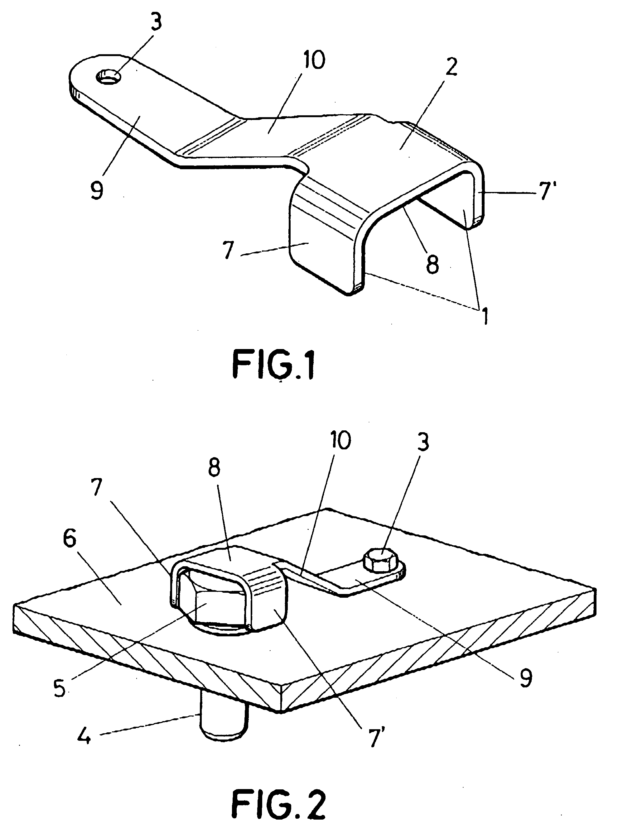
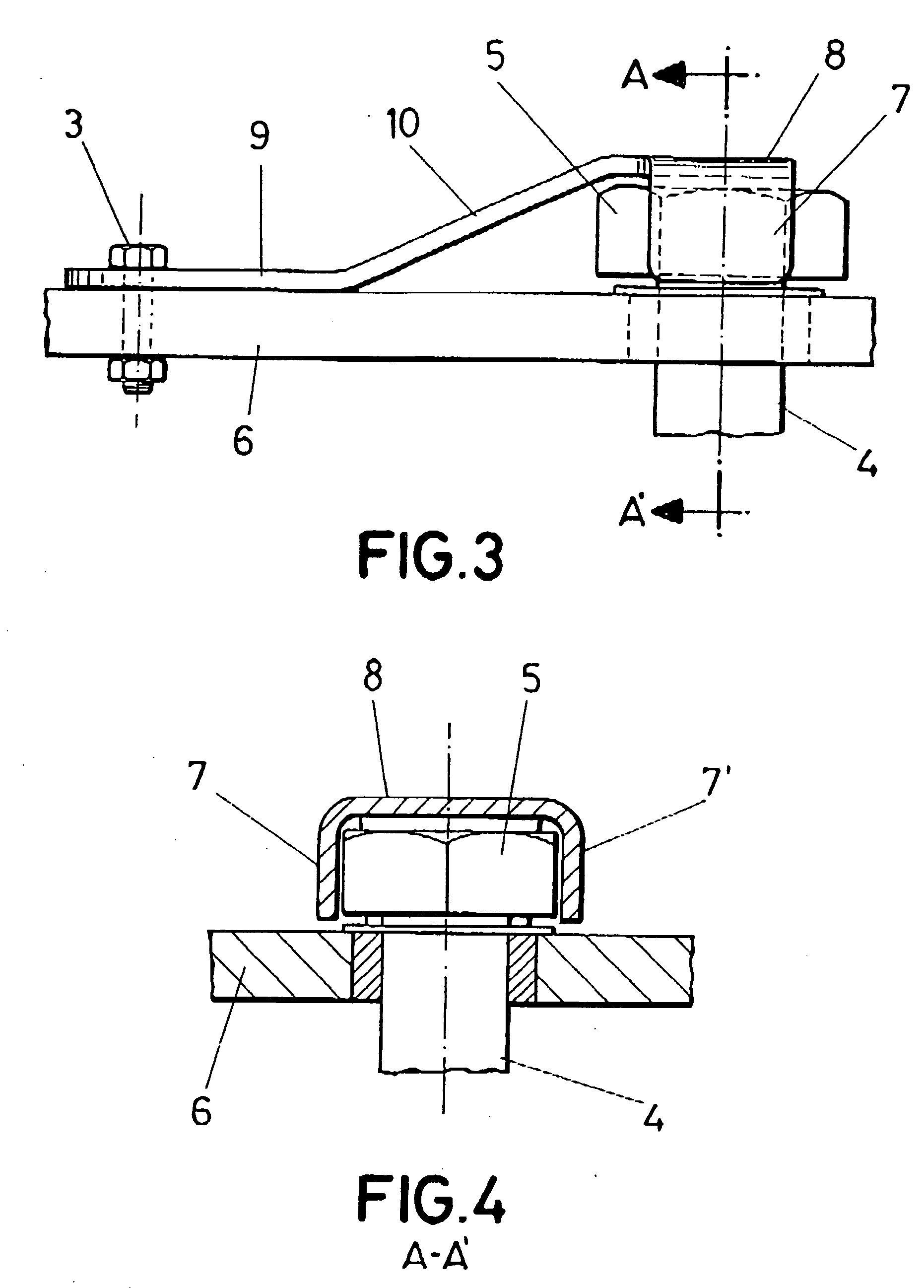
[0030]FIGS. 1 to 4 represent the invention, in which:

[0031]FIG. 1 shows a perspective view of the first embodiment,

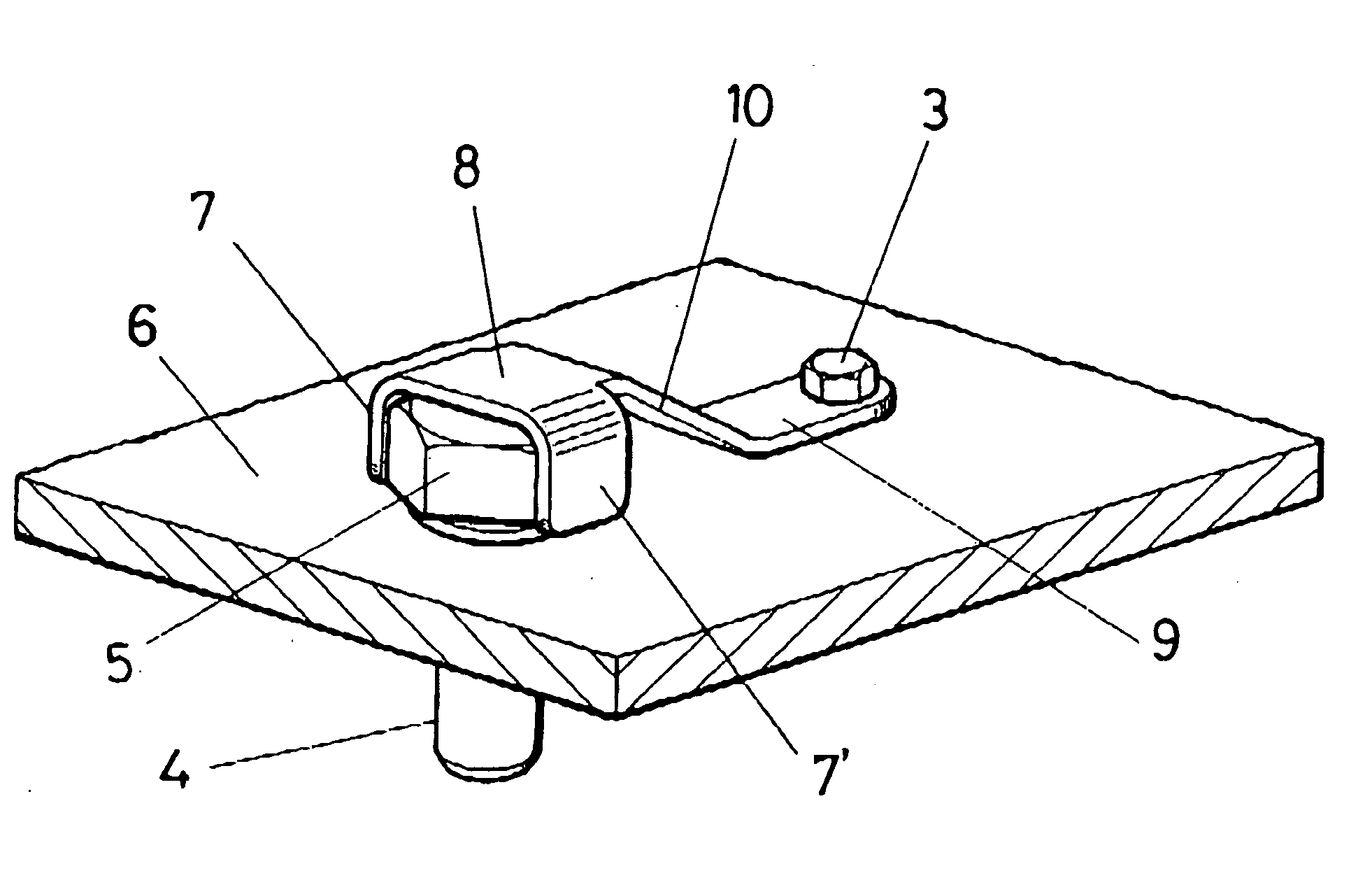
[0032]FIG. 2 shows another view in perspective of the first embodiment, in which the device appears affixed to the coupling element, as it is used,

[0033]FIG. 3 shows a view in transverse elevation of the device of the first embodiment, in which the device appears affixed to the coupling element, as it is used, and

[0034]FIG. 4 shows a view of the transverse cross-section A-A′ referenced to FIG. 3 of the device of the first embodiment, in which the device appears affixed to the coupling element, as it is used.

second embodiment

[0035]FIGS. 5 to 8 represent the invention, in which:

[0036]FIG. 5 shows a perspective view of the second embodiment,

[0037]FIG. 6 shows another view in perspective of the second embodiment, in which the device appears affixed to the coupling element, as it is used,

[0038]FIG. 7 shows a view in transverse elevation of the device of the second embodiment, in which the device appears affixed to the coupling element, as it is used, and

[0039]FIG. 8 shows a view of the transverse cross-section A-A′ referenced to FIG. 7 of the device of the second embodiment, in which the device appears affixed to the coupling element, as it is used.


PUM


Abstract

The device essentially consists of a substantially rigid piece that has a first portion (1), a second portion (2) and conventional means (3) for securing the piece onto a fastening surface (6).The first portion (1) forms a space such that once the head (5) of the coupling element (4) is introduced inside the space, the rotation of the coupling element (4) around its own axis is prevented (anti-rotation function).The second portion (2) is connected to the first portion (1) in a part of the second portion located opposite to the opening of the space through which the head (5) of the coupling element (4) is introduced. In such a way that once the piece is mounted on the head of the coupling element, the axial movement of the coupling element (4) is prevented (retention function).

Description

OBJECT OF THE INVENTION[0001]As stated in the title of this specification, the following invention relates to providing a device for ensuring of a threaded coupling element.[0002]Threaded coupling element is understood to be a coupling element of two surfaces for which the securing is carried out by means of a nut and auxiliary securing elements. A bolt, a screw or a pin can, therefore, be considered as coupling elements for the purposes of this patent.[0003]The ensuring consists of providing adequate installation means for a threaded coupling so that, in the event that the securing of the threaded coupling element fails, the coupling maintain its functions intact, at least during an allowed period of time until the failure can be corrected.[0004]According to the above definitions, the object of this patent is to provide an ensuring device for the threaded coupling element with the dual function that, once the device has been mounted in the threaded coupling, the device can, on its ...

Claims


Application Information

Patent Timeline
IPC IPC(8): F16B21/10
CPCF16B39/10F16B41/00
Inventor CABALLERO ASENSIO, MARIARAMIREZ BLANCO, GONZALO
Owner AIRBUS OPERATIONS SL
Learn More