
Fiber Optic Furcation Assembly Having Feature(s) for Cable Management

a fiber optic furcation and fiber optic cable technology, applied in the direction of optics, fibre mechanical structures, instruments, etc., can solve the problems of increasing cable congestion and heat per unit area, and affecting the routing and management of higher density cabling components, etc., to facilitate fiber optic interconnection, facilitate fiber optic cable management, and inhibit fiber optic cable assemblies from sagging

Active Publication Date: 2010-03-04
CORNING OPTICAL COMM LLC
View PDF4 Cites 22 Cited by
  • Summary
  • Abstract
  • Description
  • Claims
  • Application Information

AI Technical Summary

Benefits of technology

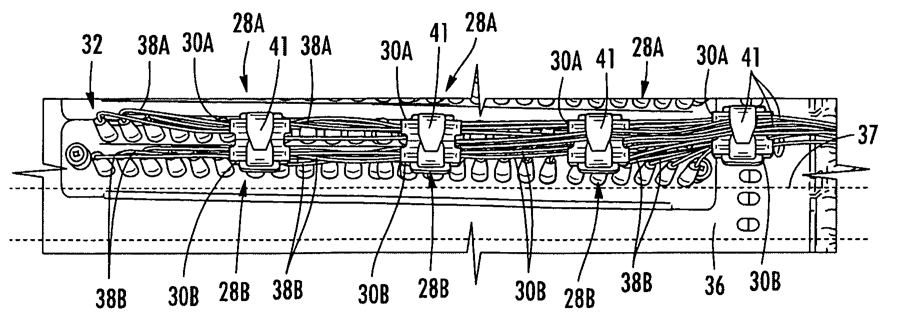
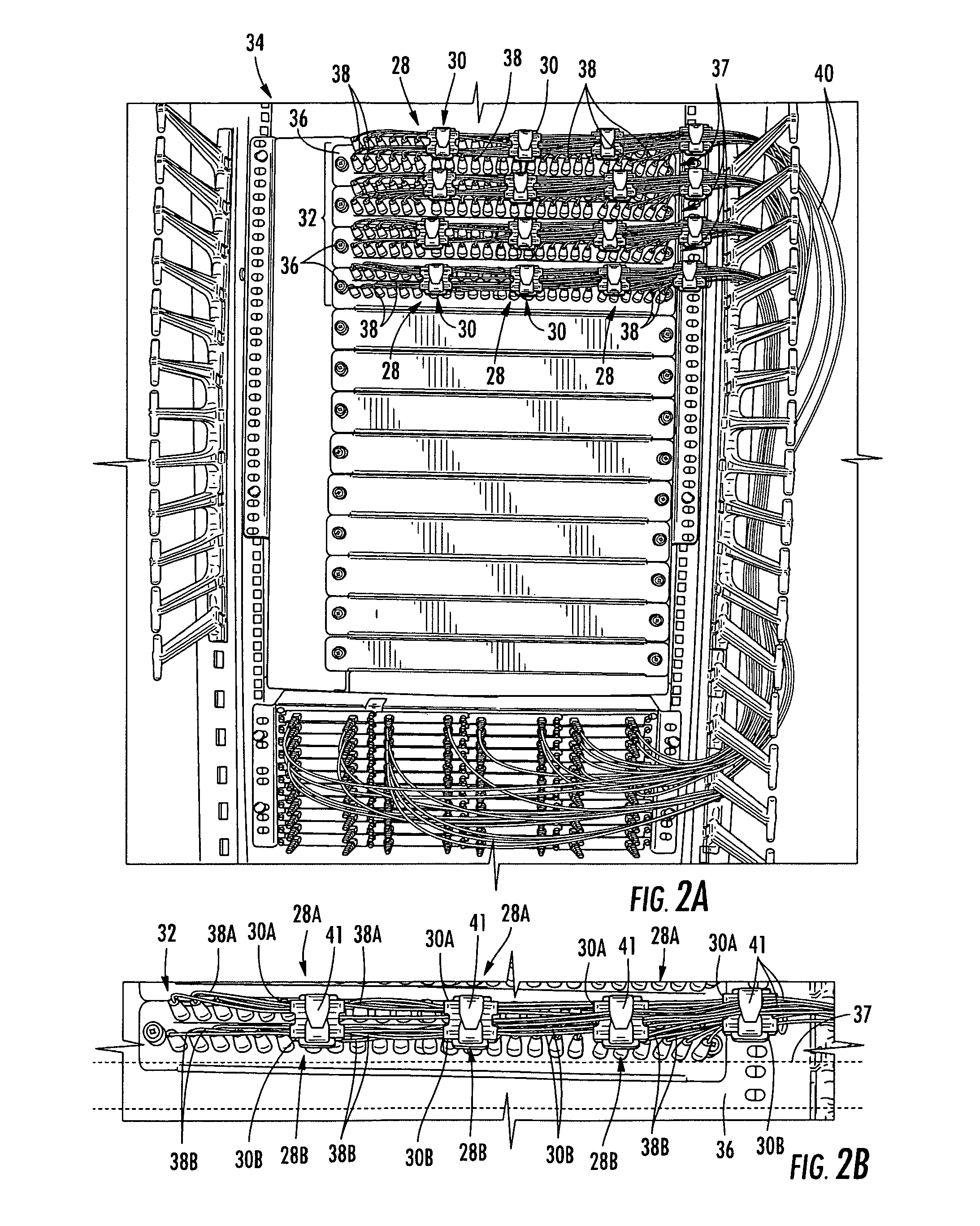
[0011]Embodiments disclosed in the detailed description include fiber optic cable assemblies having a fiber optic cable, a furcation body, and one or more furcated legs. In embodiments disclosed herein, the furcation body comprises a first end and a second end opposite the first end, the first end having the fiber optic cable extending therefrom, and the second end having one or more furcated legs extending therefrom. The furcation body can include one or more features that facilitate fiber optic cable management. These disclosed features of fiber optic cable assemblies may advantageously inhibit fiber optic cable assemblies from sagging (i.e., provide support), facilitate access to fiber optic interconnections, prevent or reduce obstruction of air flow paths between fiber optic interconnections, and / or inhibit tangling among fiber optic assemblies.

Problems solved by technology

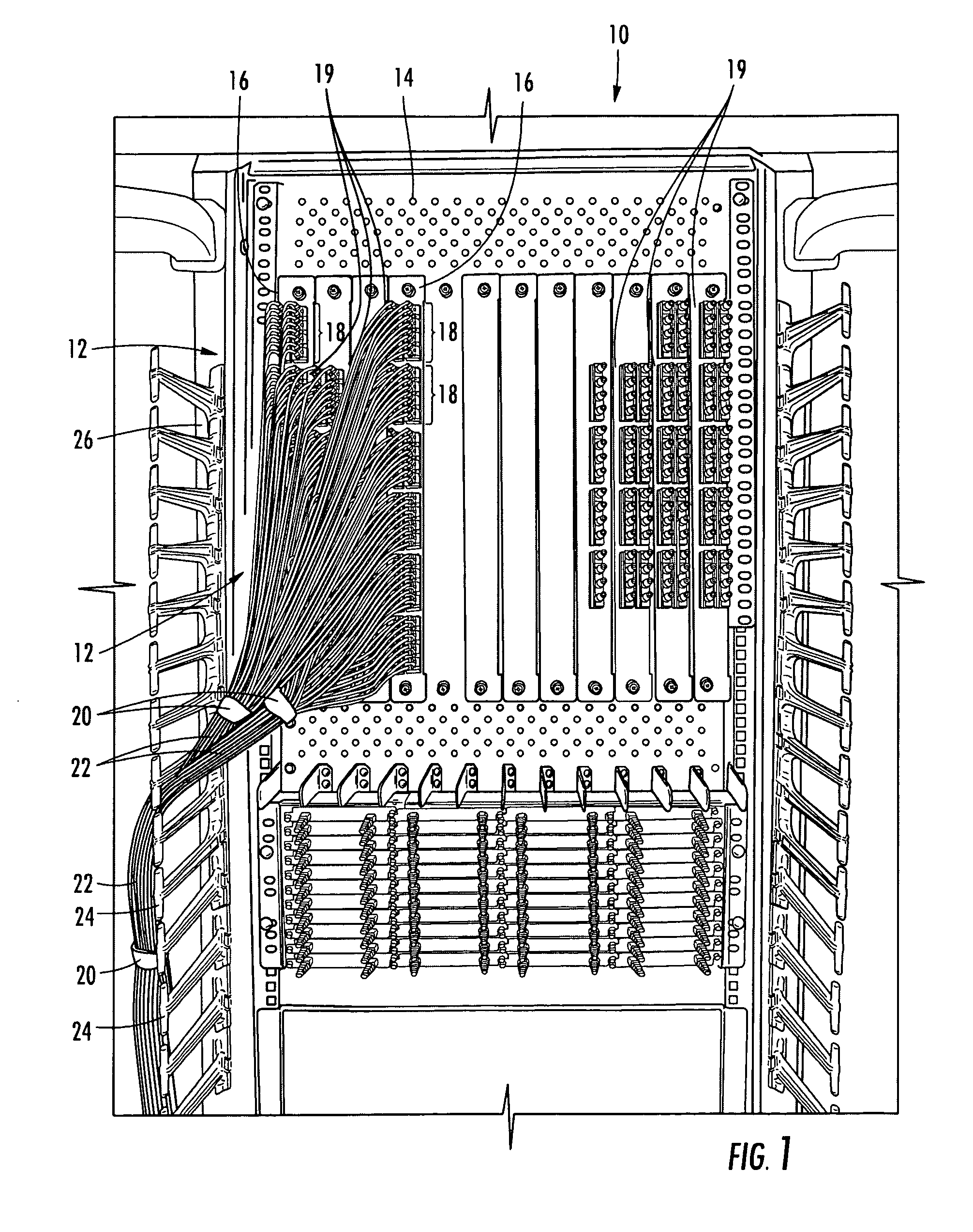
However, while use of higher density cabling components allows a larger number of interconnections to be made within a given space or area complications result.
For instance, the increased number of interconnections in the given space or area leads to an increase in cable congestion and heat per unit area due to the increased heat from fiber optic equipment and the increased cable congestion.
Moreover, the higher densities complicate cable routing and management to inhibit tangling of fiber optic cable assemblies and the like.
However, the higher density cabling components often sag into adjacent rows or columns.
Sagging cabling components can potentially adversely affect air flow, because sagging cabling components can invade air flow paths around fiber optic interconnections and thus reduce or block the air flow path.
Also sagging cabling components also make it more difficult for an installer to access an adjacent row or column of fiber optic connectors and can create tangling issues that may disrupt the system.
Moreover, the problem can be worse with horizontal arrangements.
This sagging and congestion creates access and airflow issues.
This creates issues for providing finger access to connectors on the fiber optic cables 12 and connectors or adapters 18 on the fiber optic equipment 14, and also restricts air flow causing heat generation issues.

Method used


Image

  • Fiber Optic Furcation Assembly Having Feature(s) for Cable Management
  • Fiber Optic Furcation Assembly Having Feature(s) for Cable Management
  • Fiber Optic Furcation Assembly Having Feature(s) for Cable Management

Examples


Embodiment Construction

[0011]Embodiments disclosed in the detailed description include fiber optic cable assemblies having a fiber optic cable, a furcation body, and one or more furcated legs. In embodiments disclosed herein, the furcation body comprises a first end and a second end opposite the first end, the first end having the fiber optic cable extending therefrom, and the second end having one or more furcated legs extending therefrom. The furcation body can include one or more features that facilitate fiber optic cable management. These disclosed features of fiber optic cable assemblies may advantageously inhibit fiber optic cable assemblies from sagging (i.e., provide support), facilitate access to fiber optic interconnections, prevent or reduce obstruction of air flow paths between fiber optic interconnections, and / or inhibit tangling among fiber optic assemblies.

[0012]Additional features and advantages will be set forth in the detailed description which follows, and in part will be readily appare...


PUM


Abstract

Fiber optic cable assemblies having a fiber optic cable, a furcation body, and one or more furcated legs are disclosed herein. In embodiments disclosed herein, the furcation body comprises a first end and a second end opposite the first end, the first end having the fiber optic cable extending therefrom, and the second end having one or more furcated legs extending therefrom. The furcation body can include one or more features that facilitate cable management by supporting cabling components used in making fiber optic interconnections. The cable management features of the fiber optic cable assemblies advantageously inhibit sagging, facilitate access to fiber optic interconnections, and / or improve air flow paths between fiber optic interconnections.

Description

RELATED APPLICATIONS[0001]The present application claims priority to U.S. Provisional Patent Application Ser. No. 61 / 197,068 titled “High Density Data Center Hardware Assemblies, and Components,” which is incorporated herein by reference in its entirety.[0002]The present application also claims priority to U.S. Provisional Patent Application Ser. No. 61 / 190,538 titled “High Density Data Center Hardware Assemblies, and Components,” which is incorporated herein by reference in its entirety.BACKGROUND[0003]1. Field of the Disclosure[0004]The technology of the disclosure relates to fiber optic cable management. More specifically, the disclosure relates to fiber optic cable assemblies for fiber optic cable management.[0005]2. Technical Background[0006]Benefits of optical fiber use include extremely wide bandwidth and low noise operation. Because of these advantages, optical fiber is increasingly being used for a variety of applications, including but not limited to broadband voice, video...

Claims


Application Information

Patent Timeline
IPC IPC(8): G02B6/44G02B6/00
CPCG02B6/4471
Inventor COOKE, TERRY L.DEAN, JR., DAVID L.HOUSER, CHRISTOPHER S.KLAVUHN, TORY A.MABRY, III, CLYDE B.
Owner CORNING OPTICAL COMM LLC
Learn More