
Use of Micro-Electro-Mechanical Systems (MEMS) in Well Treatments

a micro-electromechanical system and well technology, applied in the direction of survey, borehole/well accessories, construction, etc., can solve the problems of degrading cement, adversely affecting the integrity of sealant, and undesirable for use in the wellbore environmen

Active Publication Date: 2010-03-04
HALLIBURTON ENERGY SERVICES INC
View PDF99 Cites 120 Cited by
  • Summary
  • Abstract
  • Description
  • Claims
  • Application Information

AI Technical Summary

Benefits of technology

[0008]Further disclosed herein is a method comprising placing one or more Micro-Electro-Mechanical System (MEMS) sensors in a subterranean formation, placing a wellbore composition in the subterranean formation, using the one or more MEMS sensors to detect a location of at least a portion of the wellbore composition, and using the one or more MEMS sensors to monitor at least a portion of the wellbore composition.
[0009]Further disclosed herein is a method comprising placing one or more Micro-Electro-Mechanical System (MEMS) sensors in a subterranean formation using a wellbore composition, and monitoring a condition using the one or more MEMS sensors.
[0010]Further disclosed herein is a method comprising placing one or more Micro-Electro-Mechanical System (MEMS) sensors in a subterranean formation using a wellbore composition, wherein the one or more MEMS sensors comprise an amount from about 0.001 to about 10 weight percent of the wellbore composition.
[0011]Further disclosed herein is a method comprising placing one or more Micro-Electro-Mechanical System (MEMS) sensors in CO2 injection, storage or disposal well in a subterranean formation, and monitoring a condition using the one or more MEMS sensors.

Problems solved by technology

The integrity of sealant can be adversely affected by conditions in the well.
For example, cracks in cement may allow water influx while acid conditions may degrade cement.
Active, embeddable sensors can involve drawbacks that make them undesirable for use in a wellbore environment.
For example, low-powered (e.g., nanowatt) electronic moisture sensors are available, but have inherent limitations when embedded within cement.
The highly alkali environment can damage their electronics, and they are sensitive to electromagnetic noise.
Additionally, power must be provided from an internal battery to activate the sensor and transmit data, which increases sensor size and decreases useful life of the sensor.

Method used


Image

  • Use of Micro-Electro-Mechanical Systems (MEMS) in Well Treatments
  • Use of Micro-Electro-Mechanical Systems (MEMS) in Well Treatments
  • Use of Micro-Electro-Mechanical Systems (MEMS) in Well Treatments

Examples


Embodiment Construction

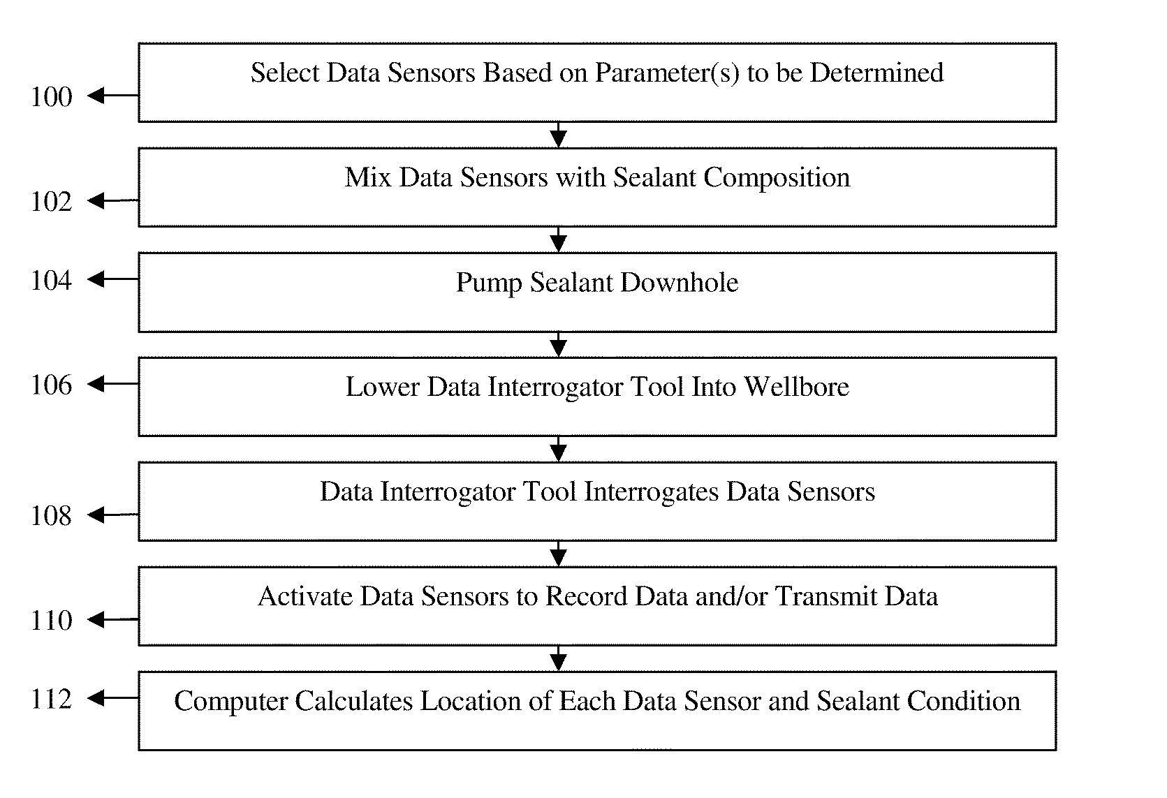
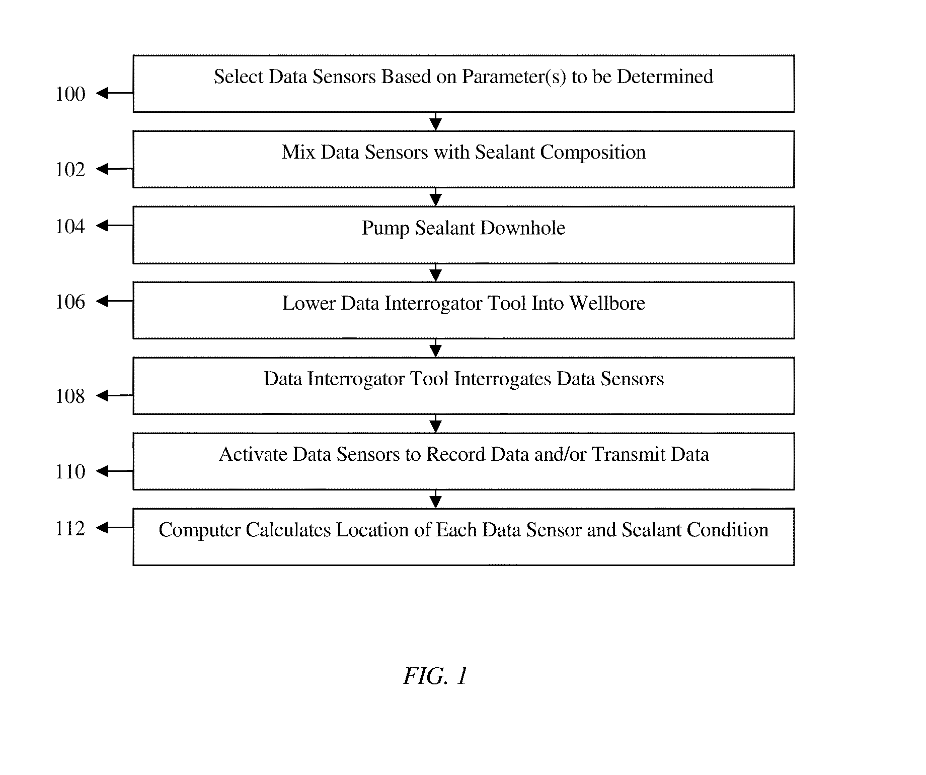
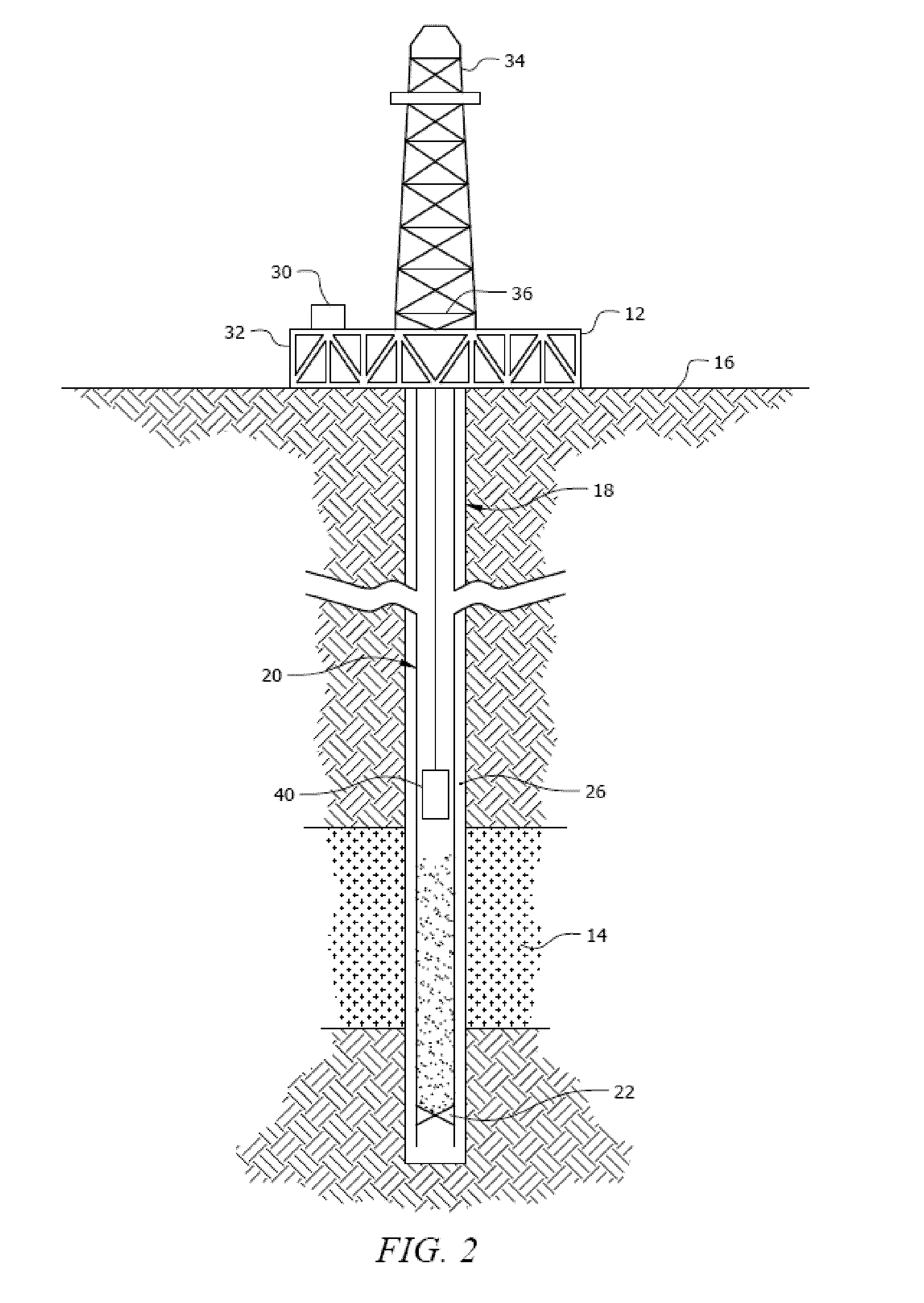
[0006]Disclosed herein is a method comprising placing a Micro-Electro-Mechanical System (MEMS) sensor in a subterranean formation, placing a wellbore composition in the subterranean formation, and using the MEMS sensor to detect a location of the wellbore composition.

[0007]Also disclosed herein is a method comprising placing a Micro-Electro-Mechanical System (MEMS) sensor in a subterranean formation, placing a wellbore composition in the subterranean formation, and using the MEMS sensor to monitor a condition of the wellbore composition.

[0008]Further disclosed herein is a method comprising placing one or more Micro-Electro-Mechanical System (MEMS) sensors in a subterranean formation, placing a wellbore composition in the subterranean formation, using the one or more MEMS sensors to detect a location of at least a portion of the wellbore composition, and using the one or more MEMS sensors to monitor at least a portion of the wellbore composition.

[0009]Further disclosed herein is a me...


PUM


Abstract

A method comprising placing a Micro-Electro-Mechanical System (MEMS) sensor in a subterranean formation, placing a wellbore composition in the subterranean formation, and using the MEMS sensor to detect a location of the wellbore composition. A method comprising placing a Micro-Electro-Mechanical System (MEMS) sensor in a subterranean formation, placing a wellbore composition in the subterranean formation, and using the MEMS sensor to monitor a condition of the wellbore composition. A method comprising placing one or more Micro-Electro-Mechanical System (MEMS) sensors in a subterranean formation, placing a wellbore composition in the subterranean formation, using the one or more MEMS sensors to detect a location of at least a portion of the wellbore composition, and using the one or more MEMS sensors to monitor at least a portion of the wellbore composition. A method comprising placing one or more Micro-Electro-Mechanical System (MEMS) sensors in a subterranean formation using a wellbore composition, and monitoring a condition using the one or more MEMS sensors.

Description

CROSS-REFERENCE TO RELATED APPLICATIONS[0001]This is a Continuation-in-Part Application of U.S. patent application Ser. No. 11 / 695,329, filed Apr. 2, 2007 and entitled “Use of Micro-Electro-Mechanical Systems (MEMS) in Well Treatments,” which is hereby incorporated by reference herein in its entirety.BACKGROUND OF THE INVENTION[0002]This disclosure relates to the field of drilling, completing, servicing, and treating a subterranean well such as a hydrocarbon recovery well. In particular, the present disclosure relates to methods for detecting and / or monitoring the position and / or condition of wellbore compositions, for example wellbore sealants such as cement, using MEMS-based data sensors. Still more particularly, the present disclosure describes methods of monitoring the integrity and performance of wellbore compositions over the life of the well using MEMS-based data sensors.[0003]Natural resources such as gas, oil, and water residing in a subterranean formation or zone are usual...

Claims


Application Information

Patent Timeline
Patent Type & Authority Applications(United States)
IPC IPC(8): E21B47/00
CPCE21B33/13E21B43/25E21B47/122E21B47/01E21B47/10E21B47/0005E21B47/005E21B47/13
Inventor RODDY, CRAIG W.COVINGTON, RICKY L.
Owner HALLIBURTON ENERGY SERVICES INC
Learn More