Fuel distribution manifold system for gas turbine engines

a gas turbine engine and manifold technology, applied in the direction of engine starters, engine/propulsion engine ignition, lighting and heating apparatus, etc., can solve the problems of excessive thermal strain on engine components, ineffective type of flexible connection lines in high temperature applications, and inability to achieve stable combustion of stagnant fuel in those lines, and achieve the effect of facilitating staged combustion and improving engine efficiency

Active Publication Date: 2010-03-04
COLLINS ENGINE NOZZLES INC
View PDF13 Cites 40 Cited by
  • Summary
  • Abstract
  • Description
  • Claims
  • Application Information

AI Technical Summary

Benefits of technology

[0009]In accordance with the subject invention, a radially outer sealing tube surrounds the radially inner fuel transfer tube. The opposed end portions of the sealing tube are statically or otherwise fixedly connected to the inlet fittings, in contrast to the dynamic connections between the fuel transfer tube and the inlet fittings. Preferably, the sealing tube includes a resilient section in the form of a bellows or similar structure for accommodating axial expansion and contraction of the sealing tube as the combustor casing thermally expands and contracts during engine operation. By surrounding the fuel transfer tube, the outer sealing tube provides leak protection with respect to the sealing means associated with the opposed end portions of the fuel transfer tube. In addition, a cover tube preferably surrounds the sealing tube of each manifold segment to protect the resilient bellows section of the sealing tube. The cover tube also helps to increase the internal pressure capacity of the resilient bellows section of the sealing tube by stabilizing the outer surface thereof.
[0010]The sealing tube can be slightly longer then the manifold segment length between fuel injector inlet fittings. As a result, the resilient bellows section of the sealing tube would be compressed when installed between the inlet fittings. This initial installation compression would be beneficial to the bellows cyclic loading life.
[0012]The subject invention is also directed to a fuel distribution manifold system for a gas turbine engine employing staged combustion, which is configured to ensure that all of the fuel lines in the manifold assembly are kept relatively cool during engine operation, even when one or more of the fuel lines is shut-off. In this regard, the manifold system includes a plurality of circumferentially spaced apart fuel injector inlet fittings that extend around a periphery of the engine. These inlet fittings include adjacent pairs of first and second inlet fittings. A manifold segment extends between adjacent pairs of first and second inlet fittings and each manifold segment includes at least first, second and third coaxially arranged fuel transfer tubes. By nesting the plural fuel transfer tubes in this manner, fuel flowing through one or more of the transfer tubes will continuously cool the fuel tubes not in use, thereby preventing stagnant fuel in those lines from coking.
[0013]The first fuel transfer tube in each manifold segment is situated to deliver fuel to a first fuel circuit of the manifold assembly formed in both the first and second inlet fittings, the second fuel transfer tube in each manifold segment is situated to deliver fuel to a second fuel circuit of the manifold assembly formed in the first inlet fitting and the third fuel transfer tube in each manifold segment is situated to deliver fuel to a third fuel circuit of the manifold assembly formed in the second inlet fitting. The flow of fuel to one or more of the three fuel circuits of the manifold assembly is controlled by a fuel control system that is adapted and configured or otherwise programmed to facilitate staged combustion over the operating cycle of the gas turbine engine, primarily to improve engine efficiency.
[0014]To accommodate the thermal expansion and contraction of the combustor casing, opposed end portions of the coaxially arranged first, second and third fuel transfer tubes of each manifold segment are dynamically connected to the inlet fittings by annular sealing means. Preferably, the annular sealing means are one or more O-rings seals seated at the opposed end portions of each of the coaxially arranged fuel transfer tubes. In addition, each manifold segment includes a sealing tube that surrounds the coaxially arranged fuel transfer tubes to provide leak protection for the system. Preferably, the opposed end portions of the sealing tube are statically connected to the inlet fittings by coupling means and the sealing tube includes a resilient bellows section for accommodating axial expansion and contraction of the sealing tube during engine operation.

Problems solved by technology

These high temperatures put a tremendous thermal strain on engine components associated with the combustor casing.
Prior art designs of this type are often plagued by vibration and fatigue.
These types of flexible connection lines are relatively ineffective in high temperature applications.
However, it has been found that stagnant fuel in the non-flowing manifold lines can heat-up and cause coking, rendering the manifold system ineffective over time.

Method used


Image

  • Fuel distribution manifold system for gas turbine engines
  • Fuel distribution manifold system for gas turbine engines
  • Fuel distribution manifold system for gas turbine engines

Examples


Embodiment Construction

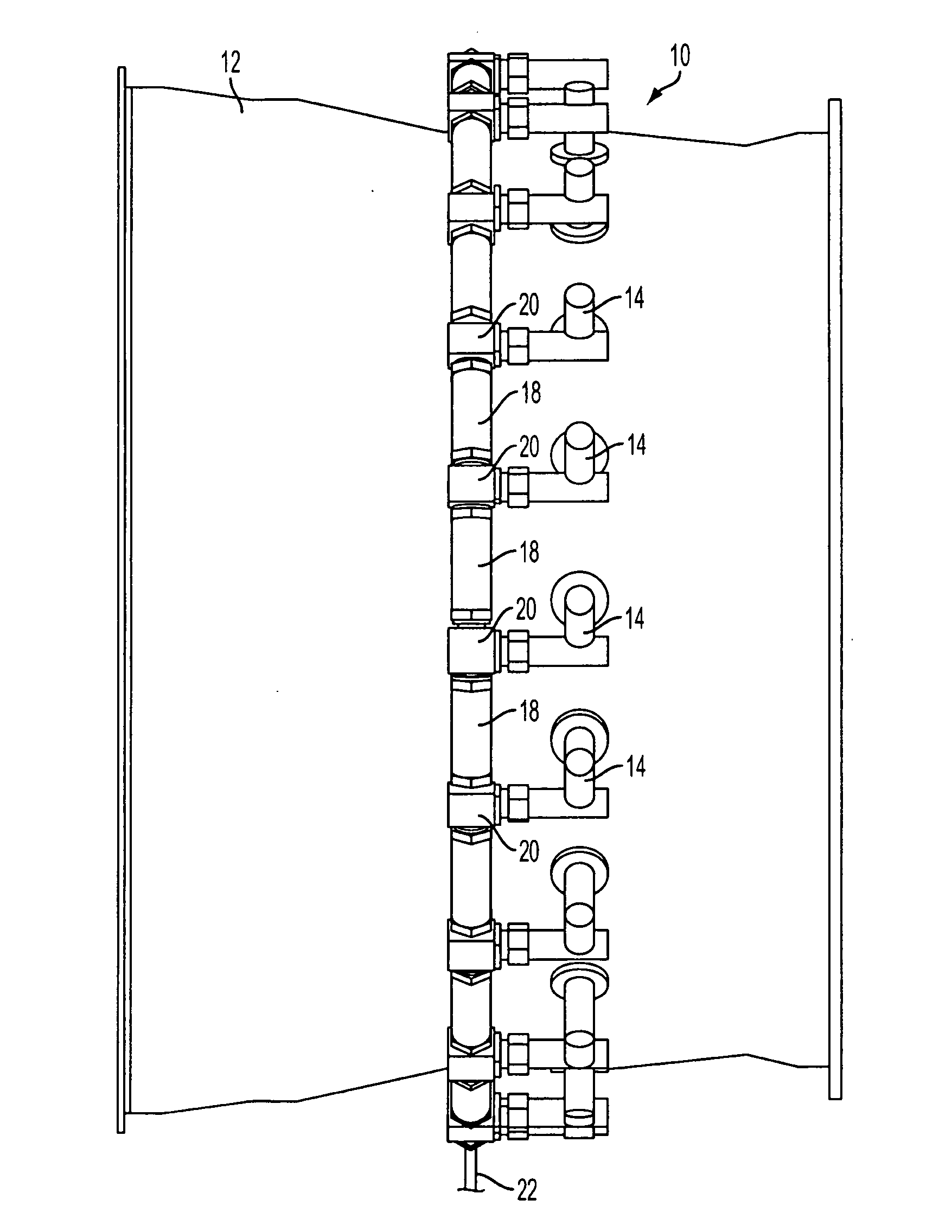
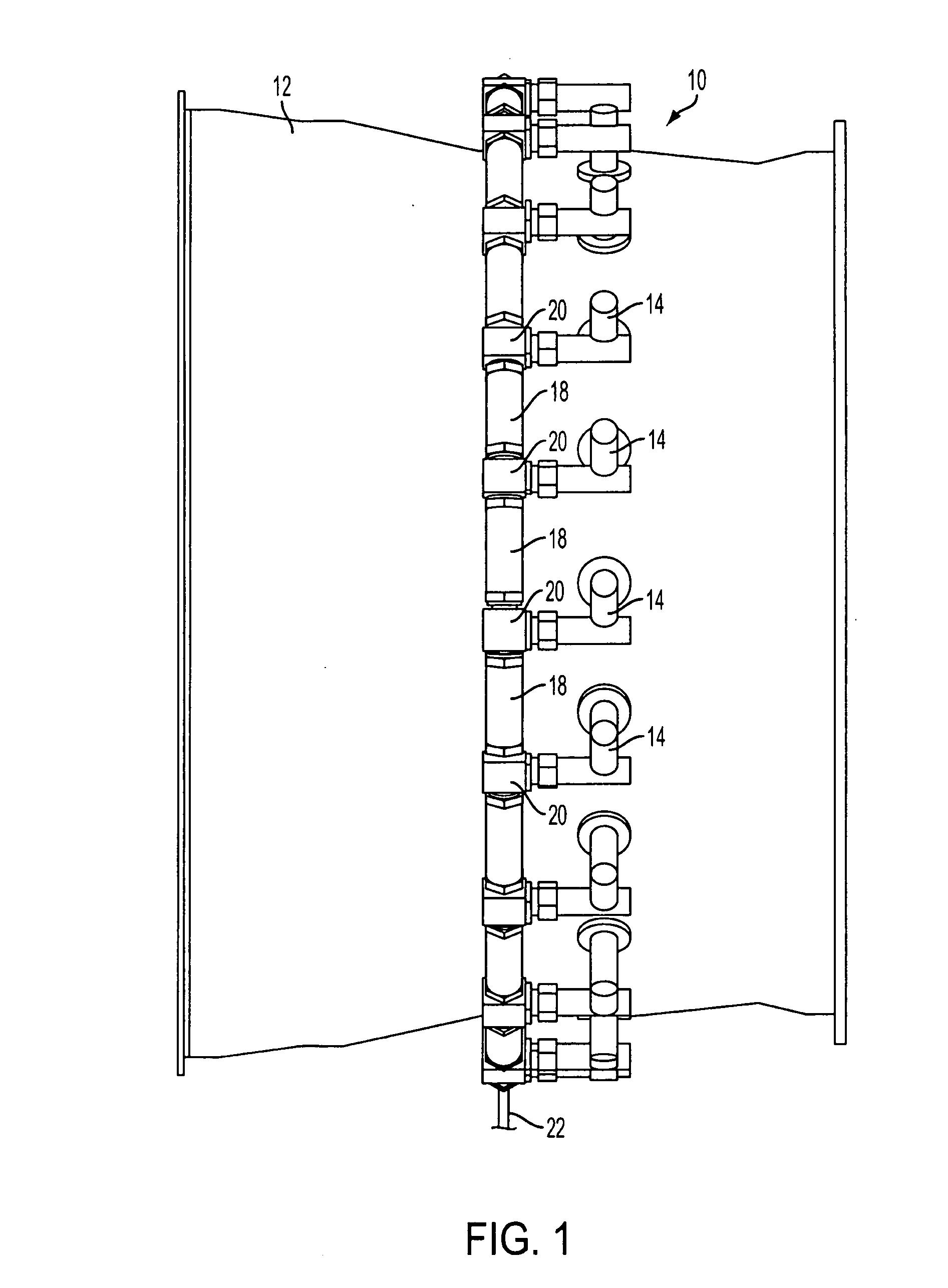
[0035]Referring now to the drawings, wherein like reference numerals identify or otherwise refer to similar structural features or elements of the various embodiments of the subject invention, there is illustrated in FIG. 1 a fuel distribution manifold system constructed in accordance with a preferred embodiment of the subject invention, and designated generally by reference numeral 10.

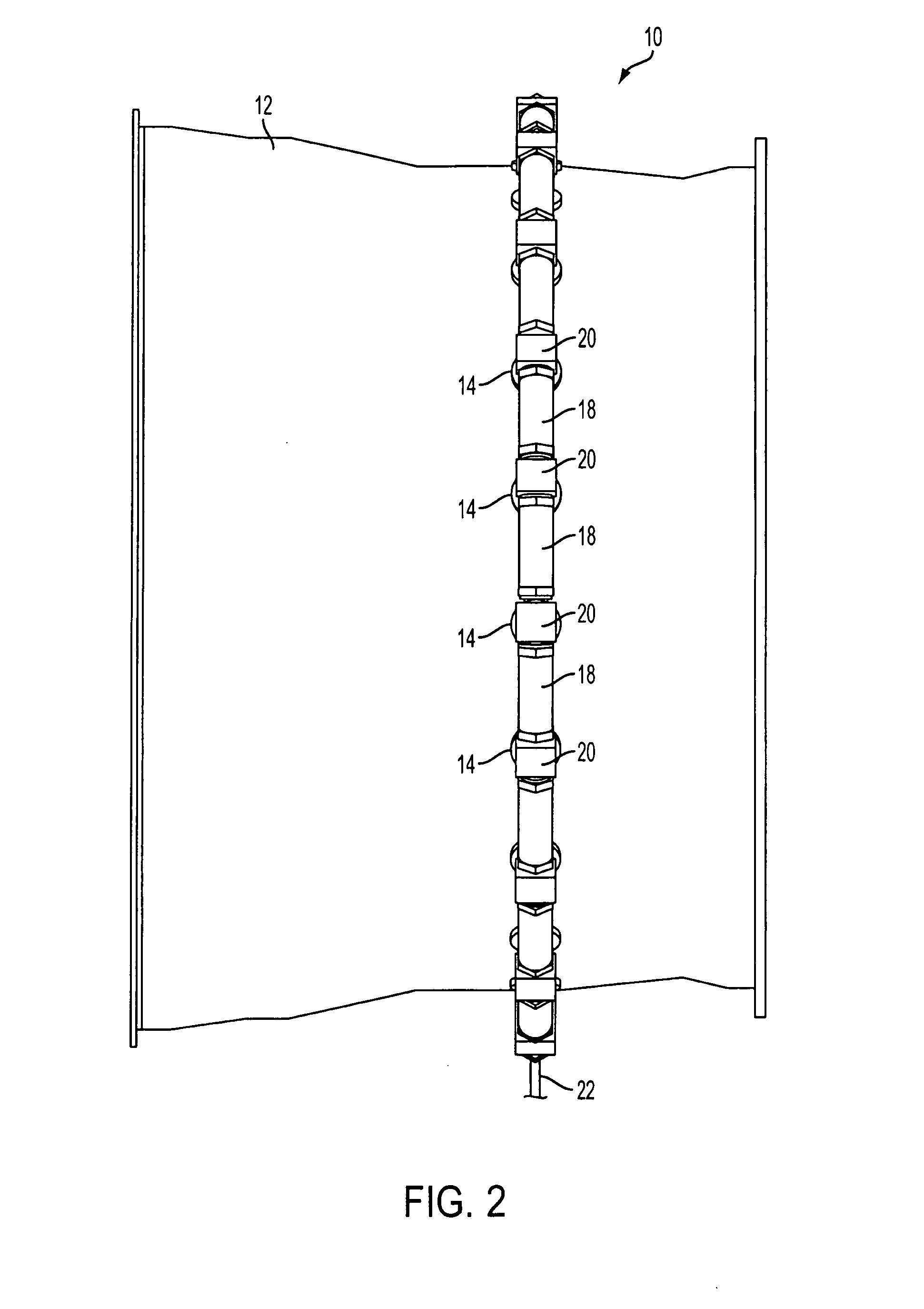
[0036]More particularly, FIG. 1 shows the fuel distribution manifold system 10 of the subject invention in an axial configuration operatively associated with the combustor casing 12 of a gas turbine engine. In this configuration, the connective portions of the fuel injector inlet fittings 20 of manifold assembly 10 extend in an axial direction to the fuel injectors 14 (i.e., parallel to the longitudinal axis of the combustor casing). In contrast to the axial configuration shown in FIG. 1, there is illustrated in FIG. 2 a radial configuration of fuel distribution manifold assembly 10. In the radial con...


PUM


Abstract

A fuel distribution manifold system for a gas turbine engine is disclosed that includes a plurality of interconnected manifold segments, each manifold segment extending between a pair of fittings, each manifold segment including at least one fuel transfer tube and a sealing tube that surrounds the at least one fuel transfer tube, wherein opposed end portions of the at least one fuel transfer tube are dynamically connected to the fittings and opposed end portions of the sealing tube are statically connected to the fittings.

Description

BACKGROUND OF THE INVENTION[0001]1. Field of the Invention[0002]The subject invention is directed to gas turbine engines, and more particularly, to a fuel distribution manifold system for a gas turbine engine configured to accommodate thermal expansion and contraction of the engine case.[0003]2. Description of Related Art[0004]The fuel manifold system of a gas turbine engine distributes fuel from a fuel control system to a plurality of fuel injectors mounted on the engine case. The fuel injectors are configured to issue atomized fuel into the combustor of the engine. It is well known that combustor inlet air temperatures are extremely high (e.g., 700° C.). These high temperatures put a tremendous thermal strain on engine components associated with the combustor casing. These engine components must structurally accommodate thermal expansion and contraction of the combustor casing during engine operating cycles.[0005]In this regard, it is well known that the fuel manifold system of a ...

Claims


Application Information

Patent Timeline
IPC IPC(8): F02C7/22F23R3/28
CPCF02C7/222F05D2230/642F05D2240/55F02M55/02F02M55/025
Inventor HAGGERTY, DANIEL T.
Owner COLLINS ENGINE NOZZLES INC
Why Eureka
Try Eureka