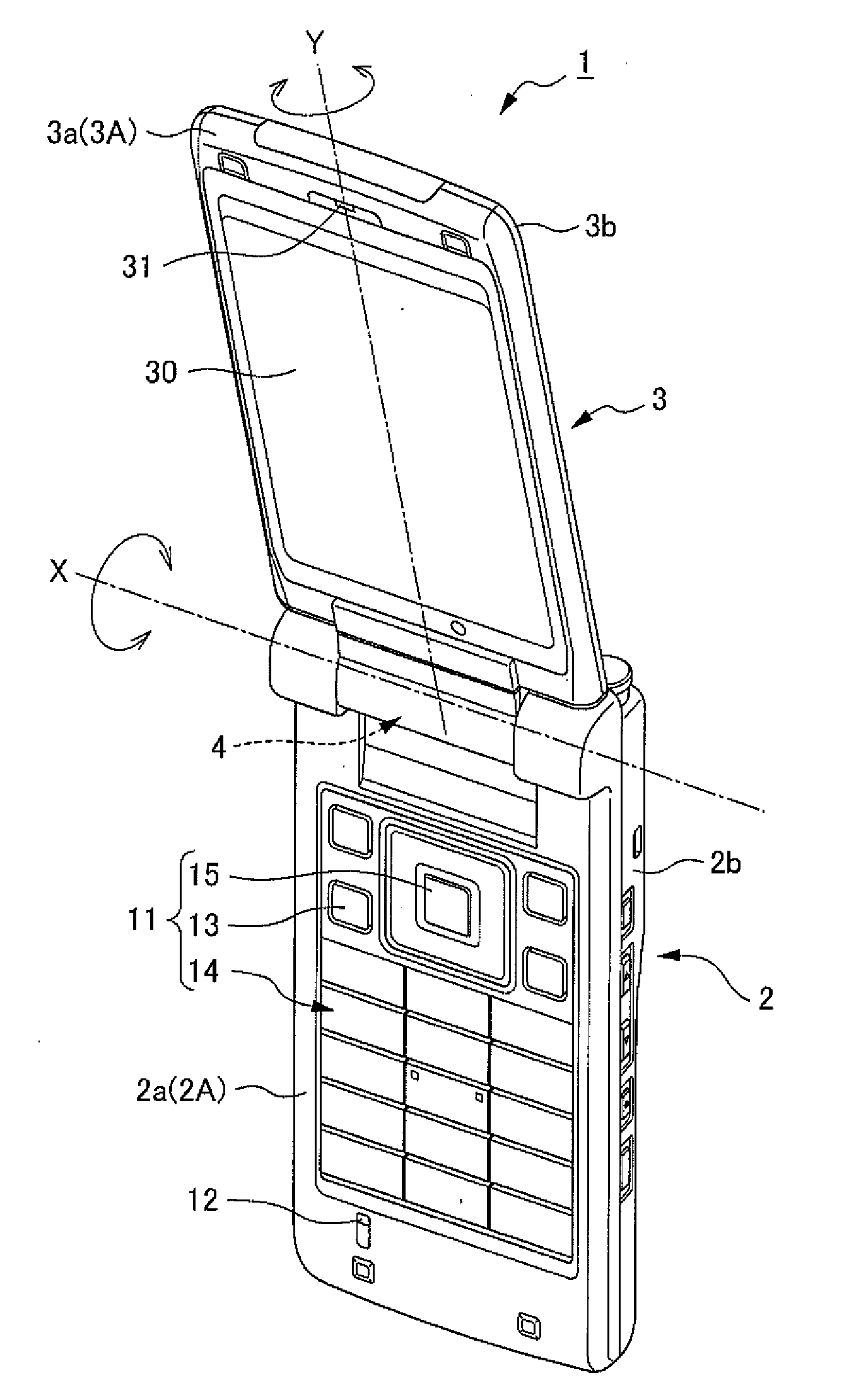
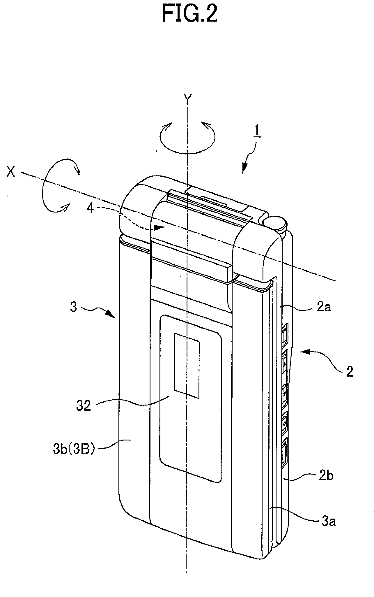
Portable Electronic Device

a portable electronic device and antenna technology, applied in the field of portable electronic devices, can solve the problems of inefficient layout of components and difficulty in and achieve the effect of stabilizing communication signal quality and reducing the fluctuation of antenna resonant frequency

Active Publication Date: 2010-02-25
KYOCERA CORP
View PDF4 Cites 1 Cited by
  • Summary
  • Abstract
  • Description
  • Claims
  • Application Information

AI Technical Summary

Benefits of technology

[0021]According to the present invention, it is possible to provide a portable electronic device that solves the problem of an inefficient layout of components, decreases fluctuation of the antenna's resonant frequency caused by the states of the bodys, and can stabilize the communication signal quality.

Problems solved by technology

As cellular telephone devices become thinner, the resonant frequency of the main antenna fluctuates dramatically from the opened state and the closed state of the cellular telephone device, making it difficult to stabilize the communication signal quality.
However, with such a configuration, it is necessary to connect the adjusting circuit directly to the main antenna, which leads to an inefficient layout of the components.

Method used


Image

  • Portable Electronic Device
  • Portable Electronic Device
  • Portable Electronic Device

Examples


first embodiment

[0063]Here, the specific configuration for solving the first issue (the resonance frequency fc of the antenna 41 fluctuating according to whether the cellular telephone device 1 is in an open or a closed state, thereby making communication unstable) of the present invention will be explained in detail below. It should be noted that, with the configuration described below, the electronic component 51 is made to be the sound output unit 31, and the sound output unit 31 and adjusting circuit 52 are electrically connected via the switch 54.

[0064]FIG. 6 is a block diagram showing an image of an entire circuit when the cellular telephone device 1 is in an opened state. Here, when conversing using the cellular telephone device 1, first the cellular telephone device 1 is opened and, by entering a conversation state using a predetermined operation, sound sent from the other party of a conversation is output from the sound output unit 31.

[0065]In addition, as shown in FIG. 6, when the cellula...

second embodiment

[0070]Next, a specific configuration for solving the second issue (the effect on the sound output unit 31 when in the closed state) of the present invention will be explained in detail below. It should be noted that, with the configuration described below, the electronic component 51 is made to be the sound output unit 31, and the sound output unit 31 and adjusting circuit 52 are electrically connected via the switch 54. In addition, it is possible to conceive of cases such as where recorded sound data is heard when using the sound output unit 31 while the cellular telephone device 1 is in the closed state, the display 30 of the display unit side body 3 is in a state where it is exposed externally, and in a closed state.

[0071]FIG. 11 is a block diagram showing an image of an overall circuit when the cellular telephone device 1 is in a closed state. It should be noted that, when the cellular telephone device 1 is in a closed state, the switch 54 is switched to electrically connect th...


PUM


Abstract

A portable electronic device is provided that reduces resonant frequency fluctuation of an antenna caused changes in the state of bodys thereof, thereby enabling the communication signal quality to be stabilized. A cellular telephone device 1 has an antenna 41 installed in an operation unit side body 2 thereof, and an electronic component 51 and an adjusting circuit 52, which is electrically connected to the electronic component 51 and adjusts the resonant frequency of the antenna 41, are installed in a display unit side body 3. A hinge portion 4 connects the operation unit side body 2 and the display unit side body 3 so as to freely change between a first state (closed state) in which the antenna 41 and electronic component 51 are capacitively coupled, and a second state (opened state) in which the antenna 41 and electronic component 51 are not capacitively coupled or capacitively coupled to a low degree.

Description

[0001]This application is based on and claims the benefit of priority from Japanese Patent Application No. 2008-045804, filed on 27 Feb. 2008, the content of which is incorporated herein by reference.BACKGROUND OF THE INVENTION[0002]1. Field of the Invention[0003]The present invention relates to an antenna-equipped portable electronic device that communicates with an external device.[0004]2. Related Art[0005]Flip type cellular (portable) telephones having a key-side body and a display-side body (composed, for example, of an LCD (liquid crystal display)) that can be folded together via a hinge mechanism have become mainstream devices. A main antenna for communication and conversation for this kind of cellular telephone device is disposed at an end portion of the key-side body or near a hinge mechanism that connects the key-side body and display-side body.[0006]Here, if the main antenna 103 is built into an end portion of the key-side body (the end portion not linked by the hinge port...

Claims


Application Information

Patent Timeline
Patent Type & Authority Applications(United States)
IPC IPC(8): H04M1/00H01Q1/24H01Q1/08H01Q1/52H04B1/38H04B1/3822
CPCH01Q1/243H01Q1/52H04M1/0225H04B1/3833H04M1/0214H01Q1/528
Inventor HIRAOKA, YOSHIAKI
Owner KYOCERA CORP
Why Eureka
Try Eureka