
Downlink MIMO transmission control method and base station apparatus

Active Publication Date: 2010-02-25
NTT DOCOMO INC
View PDF4 Cites 80 Cited by
  • Summary
  • Abstract
  • Description
  • Claims
  • Application Information

AI Technical Summary

Benefits of technology

[0036]The present invention makes it possible to improve the downlink communications efficiency.

Problems solved by technology

However, no method has yet been proposed which takes into account basic techniques such as scheduling, and the state of physical channels to be transmitted to efficiently combine such techniques and state.

Method used


Image

  • Downlink MIMO transmission control method and base station apparatus
  • Downlink MIMO transmission control method and base station apparatus
  • Downlink MIMO transmission control method and base station apparatus

Examples


Embodiment Construction

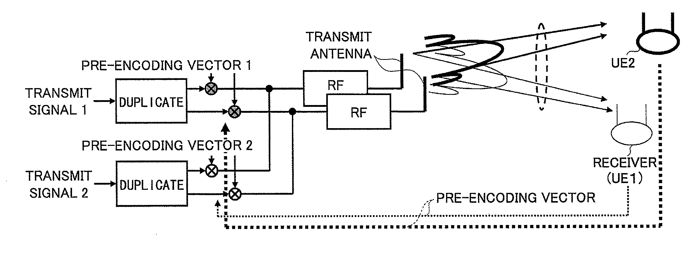
of MIMO control for a shared data channel to be transmitted to a localized-transmission type user;

[0047]FIG. 10 is Example 2 of the MIMO control for the shared data channel to be transmitted to the localized-transmission type user;

[0048]FIG. 11 is an example of MIMO control for a shared data channel to be transmitted to a distributed-transmission type user;

[0049]FIG. 12 is a diagram illustrating examples of a physical channel, to which open loop-type MIMO diversity is applied;

[0050]FIG. 13A is an exemplary configuration of a downlink L1 / L2 control channel to be transmitted using the open-loop type MIMO diversity;

[0051]FIG. 13B is an exemplary decoding of the downlink L1 / L2 control channel to be transmitted using the open-loop type MIMO diversity;

[0052]FIG. 14A is an exemplary configuration of a downlink L1 / L2 control channel to be transmitted using the open loop-type MIMO diversity;

[0053]FIG. 14B is an exemplary configuration of the downlink L1 / L2 control channel to be transmitted u...


PUM


Abstract

A method of controlling downlink transmission from a base station having multiple antennas to a mobile station having multiple antennas includes the steps of applying open loop-type MIMO diversity to one or more common control channels, an MBMS channel, and an L1 / L2 control channel; and applying closed loop-type MIMO multiplexing and / or MIMO diversity to a shared data channel.

Description

BACKGROUND OF THE INVENTION[0001]1. Field of the Invention[0002]The present invention generally relates to the field of wireless communications and specifically relates to techniques for implementing an efficient combination of various MIMO (Multiple Input Multiple Output) transmission control techniques and transmission channels, taking into account the state of each physical channel in downlink.[0003]2. Description of the Related Art[0004]HSDPA (High Speed Downlink Packet Access), which has been standardized by 3GPP, provides a maximum transmission speed of 14.4 Mbps, leading to a gradual introduction of high speed and large capacity mobile communications. However, widespread use of mobile terminals including mobile phones and of the Internet, as well as an increase in variety and sophistication of the content is leading to demands for increased capacity and frequency utilization and optimized IP traffic.[0005]LTE (Long Term Evolution), which is now being put into active use, assu...

Claims


Application Information

Patent Timeline
IPC IPC(8): H04B7/00H04W4/00H04L27/28H04J99/00
CPCH04B7/061H04L1/0625H04L1/0631H04L5/0023H04L5/0037H04B7/0697H04B7/0456H04B7/0669H04B7/068H04B7/0691H04B7/0689H04B7/0413
Inventor SAWAHASHI, MAMORUHIGUCHI, KENICHIKISHIYAMA, YOSHIHISA
Owner NTT DOCOMO INC
Learn More