
Turntable welding system with light curtain protection

a technology of turning tables and welding systems, applied in the field of multi-cell robotic welding systems, can solve the problems of increasing production time and costs, idle welding robots, and occupying substantial floor space of conventional robotic welding systems, and achieve the effect of preventing human injury

Inactive Publication Date: 2010-02-25
HONDA MOTOR CO LTD
View PDF37 Cites 27 Cited by
  • Summary
  • Abstract
  • Description
  • Claims
  • Application Information

AI Technical Summary

Benefits of technology

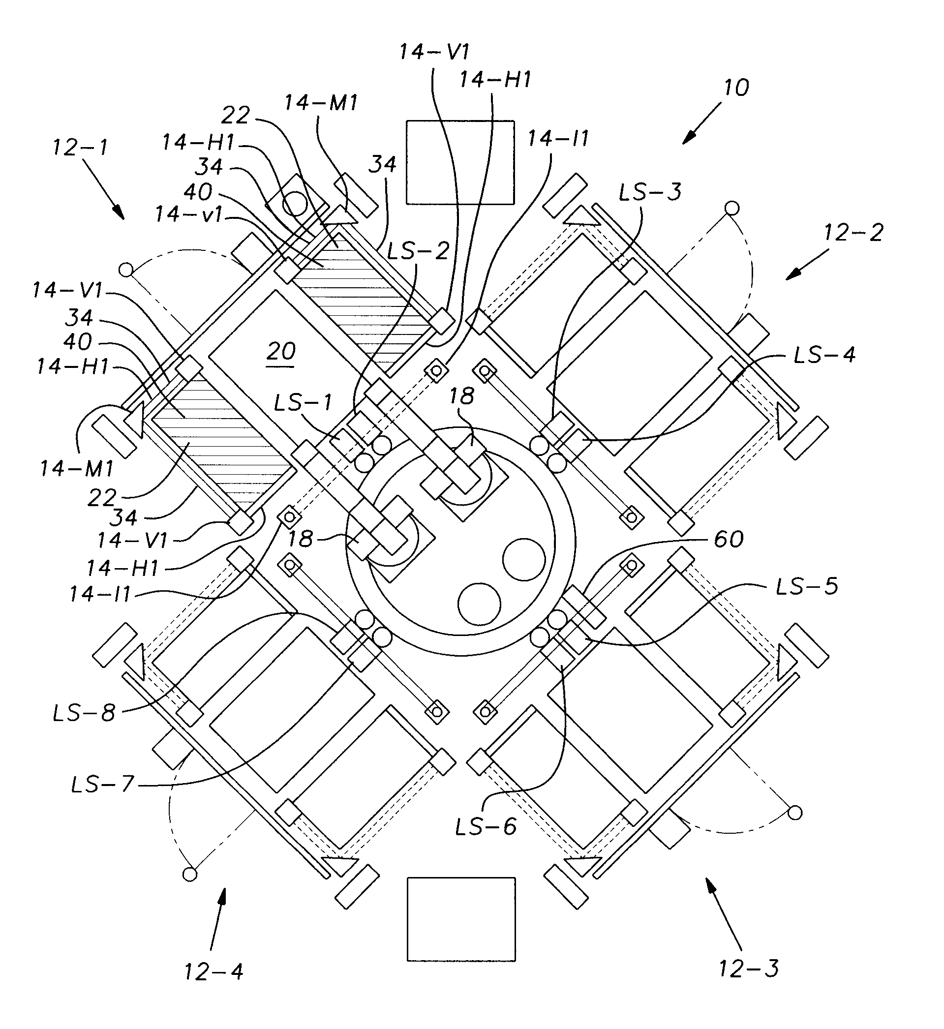
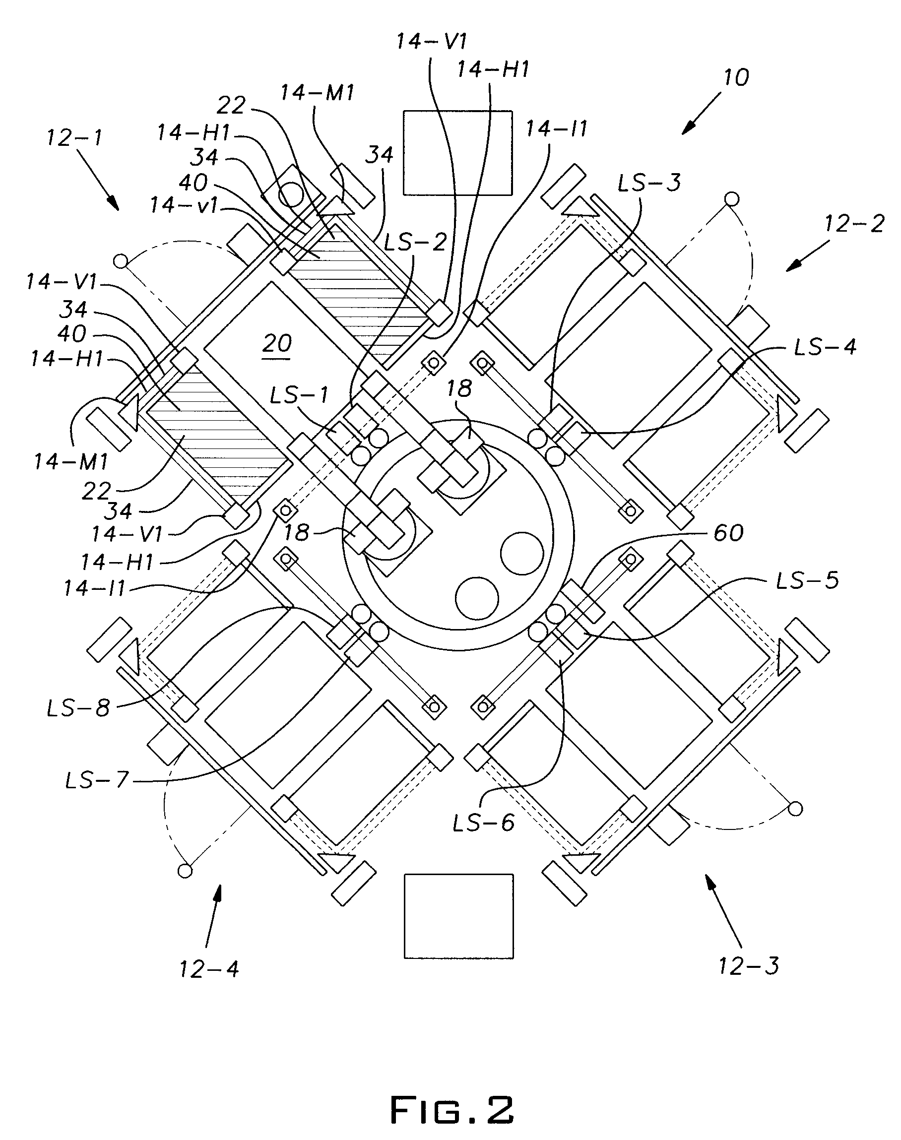
[0009]In accordance with yet another aspect, the present invention further provides a method to permit humans and a rotatable robot access to work areas. Specifically, the present invention includes an arrangement of light curtains that automatically activate and deactivate depending on a position of the robot. When activated, the light curtains create a safety curtain that detects entry into the work area. When the safety curtain is broken or disrupted, such as when a human enters the work area, power is removed from the robot thereby preventing injury to the human.

Problems solved by technology

A disadvantage of this process is that the welding robot(s) is idle during the removal of the first fixture from the welding area and the placement of the subsequent fixture into the welding area.
This in turn increases production time and costs.
Further, conventional robotic welding systems take up substantial floor space due to the arrangement of the welding robot with respect to the welding cells or stations.
This leads to increased manufacturing costs due the substantial floor space required by the system.

Method used


Image

  • Turntable welding system with light curtain protection
  • Turntable welding system with light curtain protection
  • Turntable welding system with light curtain protection

Examples


Embodiment Construction

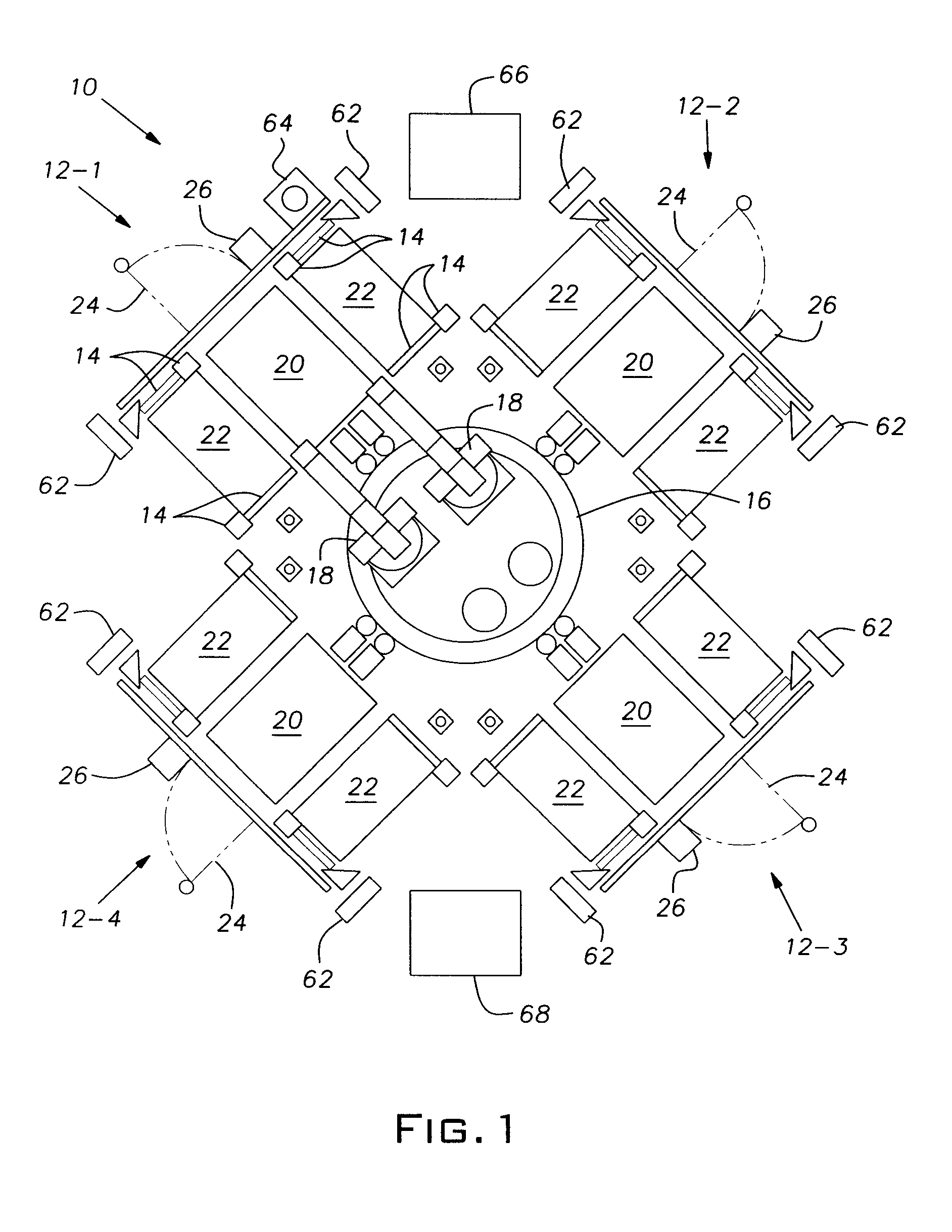
[0019]Referring now to the drawings, FIG. 1 shows a schematic overview of a turntable welding system 10 that includes, multiple welding cells or stations 12-1, 12-2, 12-3, 12-4 (hereinafter collectively referred to as “welding cells 12-X”), multiple safety-light curtains 14, a turntable 16, and multiple welding robots 18.

[0020]The multiple welding cells 12-X are equidistantly spaced in a circular arrangement. In the embodiment shown in the figures there is a first 12-1, a second 12-2, a third 12-3, and a fourth 12-4 welding cell, thus, the welding cells 12-X are spaced in 90° intervals. It should be noted, however, that the present invention is not dependent on the number of welding cells. The number of welding cells may vary depending on the application. Thus, the embodiment shown in the figures is for illustrative purposes only and is not intended to limit the scope of the present invention. The welding cells 12-X contain equipment commonly known in the art, such as, a lift hoist ...


PUM

PropertyMeasurementUnit
perimeteraaaaaaaaaa
perimeteraaaaaaaaaa
timeaaaaaaaaaa

Abstract

A robotic welding system is provided that includes multiple welding cells equidistantly spaced in a circular arrangement, multiple perimeter light curtains to provide safety protection around the welding cells, a turntable centrally located in the circular arrangement, and multiple welding robots attached to the turntable. The welding system further includes a first welding process and a second welding process whereby both the first welding process and the second welding process each include a primary welding operation and a secondary welding operation whereby the turntable rotates between the welding cells to perform the primary and secondary welding operations.

Description

BACKGROUND OF THE INVENTION[0001]1. Field of the Invention[0002]The present invention relates to a welding machine and more specifically, to a multi-cell robotic welding system wherein at least one welding robot is rotated, via a turntable, to each cell to perform a welding operation.[0003]2. Description of Related Art[0004]In a conventional robotic welding system typically a fixture containing components to be welded into a welded assembly are transported to a welding area so a welding robot or robots can perform a welding process. The welded assembly must be removed from the welding area so a subsequent fixture with components for a subsequent welded assembly can undergo the welding process. A disadvantage of this process is that the welding robot(s) is idle during the removal of the first fixture from the welding area and the placement of the subsequent fixture into the welding area. This in turn increases production time and costs.[0005]Further, conventional robotic welding syst...

Claims


Application Information

Patent Timeline
Patent Type & Authority Applications(United States)
IPC IPC(8): B23K28/00B23K37/04
CPCB23K28/00B23K37/0247B25J19/06B23K37/047B25J9/0096B23K37/04
Inventor CHARBEL, GEORGEISHIHATA, YOSHINORIZOLDAK, JULIA
Owner HONDA MOTOR CO LTD
Learn More