
Systems for reducing exhalation pressure in a mask system

a mask system and exhalation pressure technology, applied in the field of mask system exhalation pressure reduction systems, can solve the problems of unnatural constant pressure, poor comfort, and many patients' difficulty in breathing out against pressure, and achieve the effect of improving comfor

Active Publication Date: 2010-02-25
RESMED LTD
View PDF19 Cites 33 Cited by
  • Summary
  • Abstract
  • Description
  • Claims
  • Application Information

AI Technical Summary

Benefits of technology

[0039]One aspect of the invention relates to a system for reducing exhalation pressure that may fit in an existing mask or airway path.
[0044]An even further aspect of the present invention relates to a mechanical, or electromechanical, self-contained system that systematically modifies the pressure waveform output at the mask for the purpose of improving comfort, specifically that it reduces the relative mask pressure during exhalation (or increases the relative mask pressure on inspiration) The system may be powered by batteries or AC power.
[0047]Another aspect of the invention is to systematically manipulate the pressure-flow waveform to improve comfort.
[0049]One aspect of the present invention provides a mask system that reduces exhalation pressure without reliance on the flow generator. In one sample embodiment, the mask system detects the end of exhalation, and returns mask pressure to CPAP, without reliance on the flow generator. In another sample embodiment, the mask system comprises a mask incorporating valve functions. In yet another sample embodiment, the mask system comprises a normal mask, and a special valve arrangement that can be located on the mask or along the air pipe.

Problems solved by technology

Although CPAP provides effective therapy, compliance rates are suboptimal.
The constant pressure provided feels unnatural and many patients have difficulty breathing out against the pressure.
Current vented masks can have a high airflow causing excess noise, airflow and high power requirements.
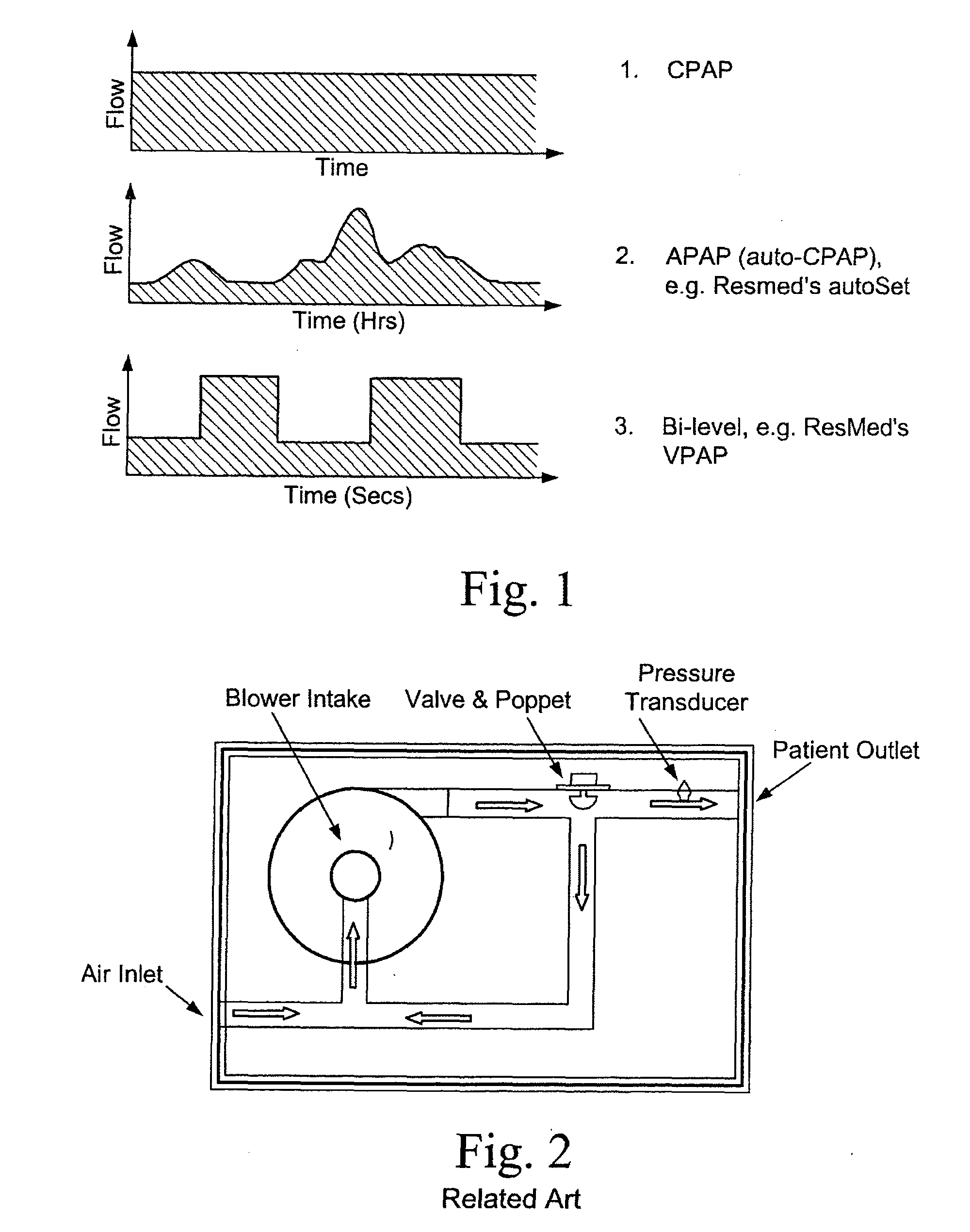
The current solutions are complex and relatively expensive, involving a special flow generator that reduces the pressure on exhalation (e.g. Bi Level Flow Generator).
While some can afford expensive therapy many of these people are on pensions or Social Security and have limited spending money for therapy.
Patients may not be able to afford the high level technology and may miss out on therapy altogether.
There are currently no lower technology solutions for flow or pressure reduction or modification that the patient can use on their current CPAP flow generator.
There is currently no low-level technology that has the potential to control pressure and flow on a breath-by-breath basis to improve breathing comfort on CPAP.
There is no evidence that pressure swing reductions is enough to improve compliance significantly.
In fact, there is very little information on the effect of pressure swing reductions on compliance.
This means there is a delay in the response time of the CPAP machine from exhalation to inhalation.
There have been some problems with PEEP valves as the preload deformation of the spring has to be relatively large to achieve the clinical range of pressures.
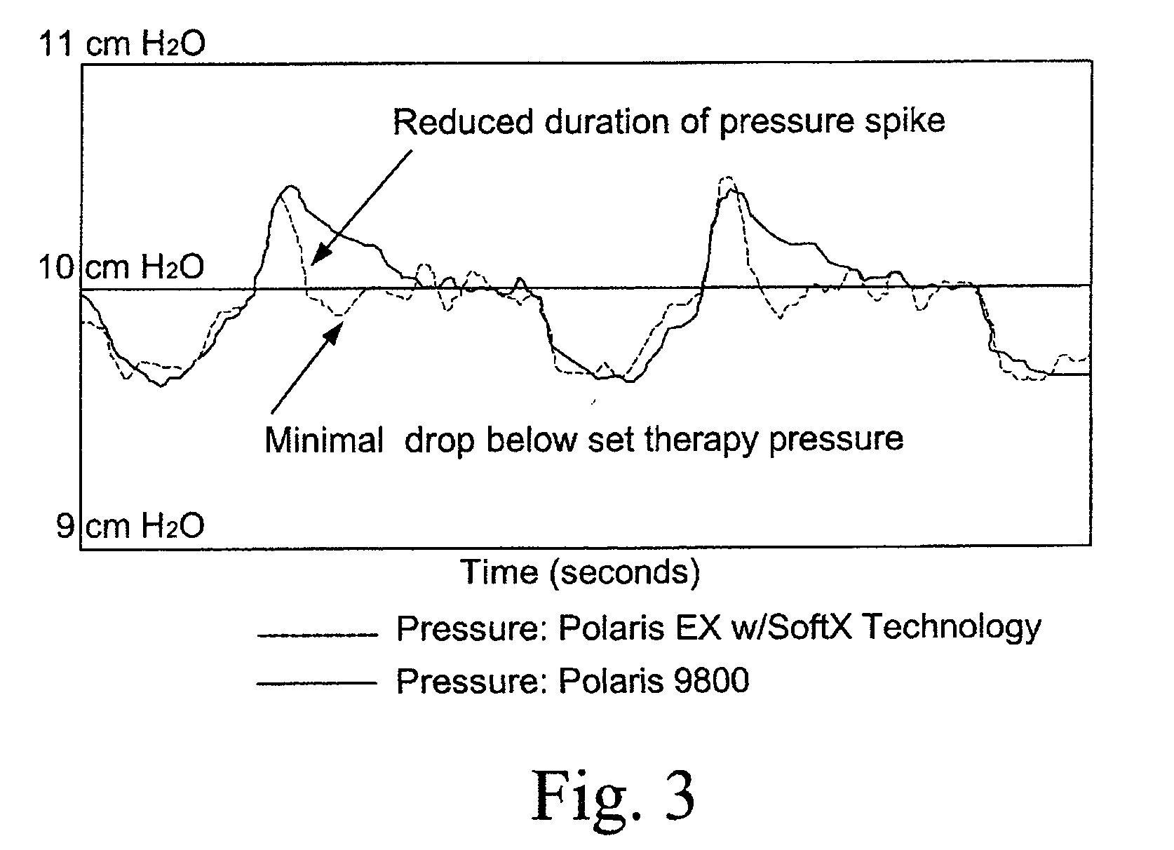
They do not relieve the pressure below the treatment pressure during expiration.
The main disadvantages are that they are loud and waste treatment pressure and humidified air.
They are also large and not aesthetically pleasing.
In a CPAP application, this is more complex as the pressure is not stored.
This complicates triggering and the device.
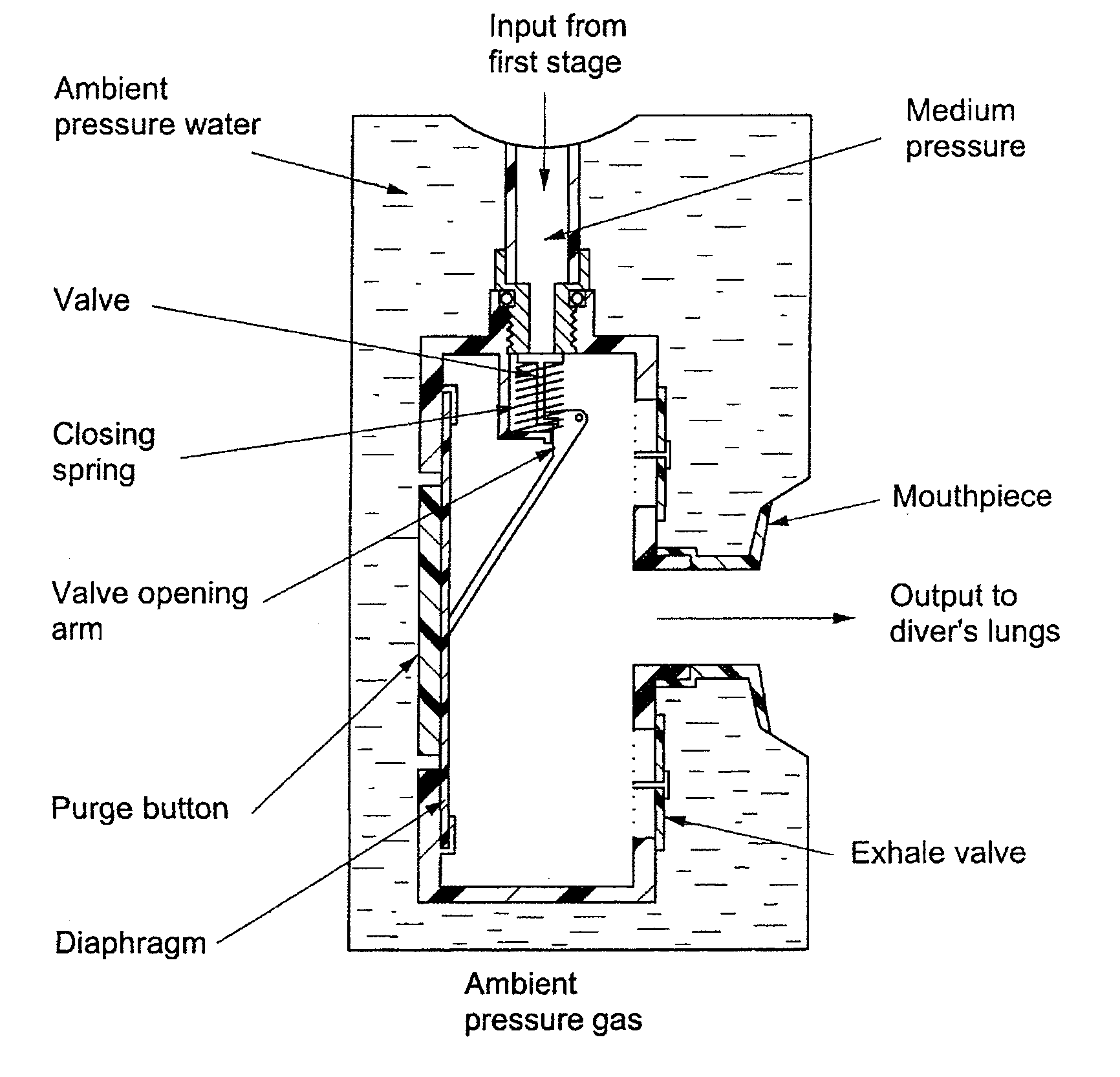
This means that the diaphragm cannot be placed between the airway pressure and atmospheric pressure (in the case of scuba—water pressure).
Application of demand valves to CPAP devices would involve many design challenges like triggering, comfort, flow generator compatibility, vent flow rate etc.
The solenoid device is disclosed as being implemented as a fluid flow control valve, and is not applicable to pressure relief as it would not relieve pressure on its own.
However, the construction of a pressure regulation valve is more complicated than a PEEP valve.
The problem with this kind of valve is that it creates a loud cyclic variation.
Additionally it only regulates the pressure, but does not relieve the pressure below the treatment pressure.
There are no inexpensive alternatives to the currently available, expensive, high-level technology solutions for breathing comfort compliance.
Cost is a major compliance issue for therapy.
There are also no low-level technology breathing comfort devices currently available that are directed to improving compliance.

Method used


Image

  • Systems for reducing exhalation pressure in a mask system
  • Systems for reducing exhalation pressure in a mask system
  • Systems for reducing exhalation pressure in a mask system

Examples


Embodiment Construction

[0091]The following description is provided in relation to several embodiments which may share common characteristics and features. It is to be understood that one or more features of any one embodiment may be combinable with one or more features of the other embodiments. In addition, any single feature or combination of features in any of the embodiments may constitute additional embodiments.

[0092]In this specification, the word “comprising” is to be understood in its “open” sense, that is, in the sense of “including”, and thus not limited to its “closed” sense, that is the sense of “consisting only of”. A corresponding meaning is to be attributed to the corresponding words “comprise”, “comprised” and “comprises” where they appear.

[0093]The term “air” will be taken to include breathable gases, for example air with supplemental oxygen. It is also acknowledged that the blowers described herein may be designed to pump fluids other than air.

[0094]Any type of relative pressure reduction...


PUM


Abstract

An apparatus for improving patient comfort during CPAP therapy includes a venting arrangement arranged to reduce expiratory pressure. A mask system for providing CPAP therapy to a patient includes a mask; a flow generator to provide a flow of pressurised breathable gas; a tube to connect the mask to the flow generator; and a venting arrangement arranged to reduce expiratory pressure.

Description

CROSS REFERENCE TO RELATED APPLICATIONS[0001]This application claims priority to Australian Provisional Applications 2006904898, 2006905948 and 2006906404 filed Sep. 7, 2006, Oct. 26, 2006, and Oct. 27, 2006, respectively.FIELD OF THE INVENTION[0002]The present invention relates to systems and methods for reducing exhalation pressure in a mask system used to deliver a pressurized flow of breathable gas to a patient.BACKGROUND OF THE INVENTION[0003]Obstructive sleep apnoea (OSA) is a sleep breathing disorder where the upper airway collapses during sleep. Most patients diagnosed with OSA are treated with continuous positive airway pressure (CPAP), which acts as an air splint to hold the upper airway open. This is delivered to the patient with a flow generator and mask system while they sleep.[0004]Although CPAP provides effective therapy, compliance rates are suboptimal. The constant pressure provided feels unnatural and many patients have difficulty breathing out against the pressure...

Claims


Application Information

Patent Timeline
IPC IPC(8): A61M16/20
CPCA61M16/06A61M16/20A61M16/208A61M2205/0266A61M16/0611A61M16/209
Inventor MEYNINK, SOFIETJEDAVIES, BRUCE RICHARDMORRISONHENRY, ROBERT EDWARDVELISS, LEE JAMES
Owner RESMED LTD
Learn More