
Industrial robot with pressurized air supply in balancing device

Active Publication Date: 2010-02-25
ABB (SCHWEIZ) AG
View PDF8 Cites 31 Cited by
  • Summary
  • Abstract
  • Description
  • Claims
  • Application Information

AI Technical Summary

Benefits of technology

[0016]It is an object of the invention is to improve the usability of industrial robots in environments with high humidity. The problem to be solved is to eliminate the risk of corrosion especially within a spring balancing unit comprised in the robot.

Problems solved by technology

If a robot is operating in an environment with high humidity, there is a risk that moisture is sucked in through any sealing due to this vacuum.
The same problem arises when a robot is working in an application where there is a hundred percentage of humidity.
Then, there is a risk that liquid on sealing surfaces is sucked in due to this vacuum.
When this occurs in a balancing cylinder comprising a worn sealing, there is even a risk that liquid is pouring into the cylinder.
Corrosion within a balancing cylinder results in malfunction, which causes a negative impact on the life time of a spring balancing device.
These needs cannot be fulfilled by the balancing systems according to the above-mentioned prior art.

Method used


Image

  • Industrial robot with pressurized air supply in balancing device
  • Industrial robot with pressurized air supply in balancing device
  • Industrial robot with pressurized air supply in balancing device

Examples


Embodiment Construction

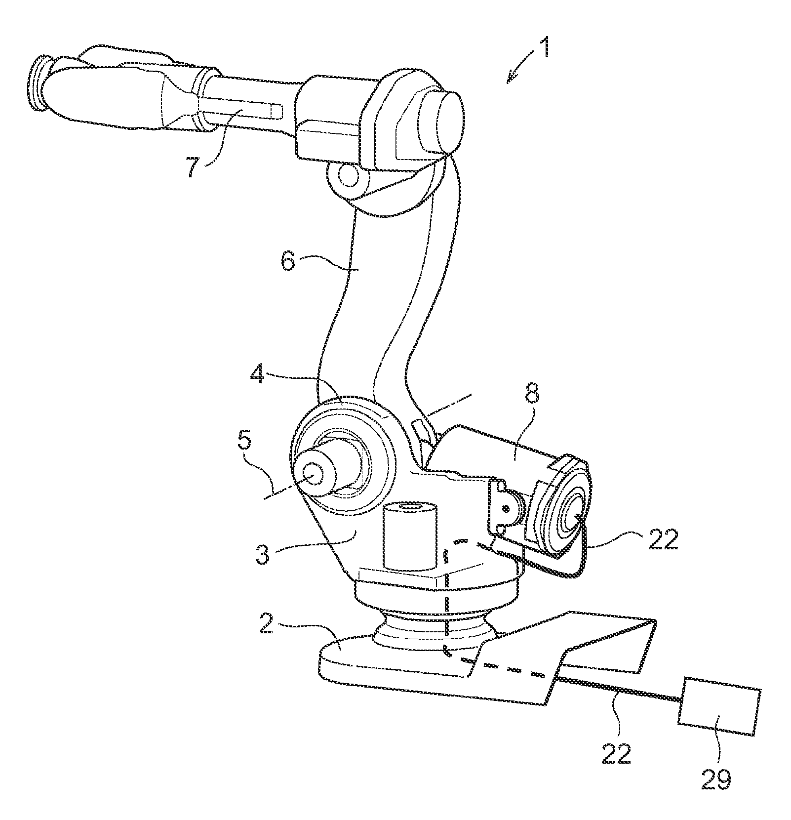
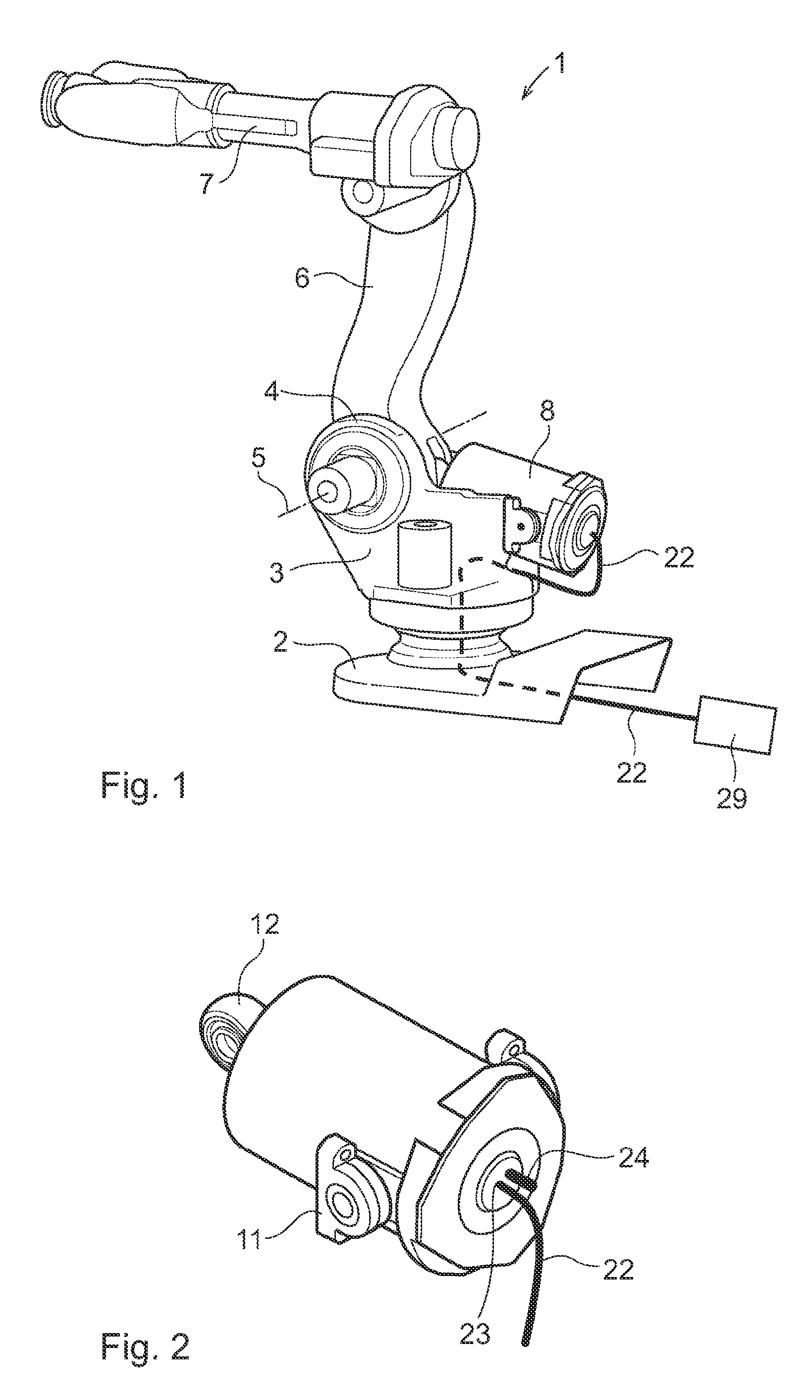
[0040]An industrial robot 1 (FIG. 1) comprises a robot foot 2, a stand 3 arranged pivoting on the robot foot 2 and a first robot arm 6 is connected to a joint 4 on the stand 3. The first robot arm 6 is pivoted around a horizontal axis 5 of rotation in the joint 4 and supports a second robot arm 7. The first 6 and the second arm 7 are arranged for relative movement during operation of the robot. The robot further comprises a balancing device 8 connected to pressurized air supply means 29 and this will be described in detail below.

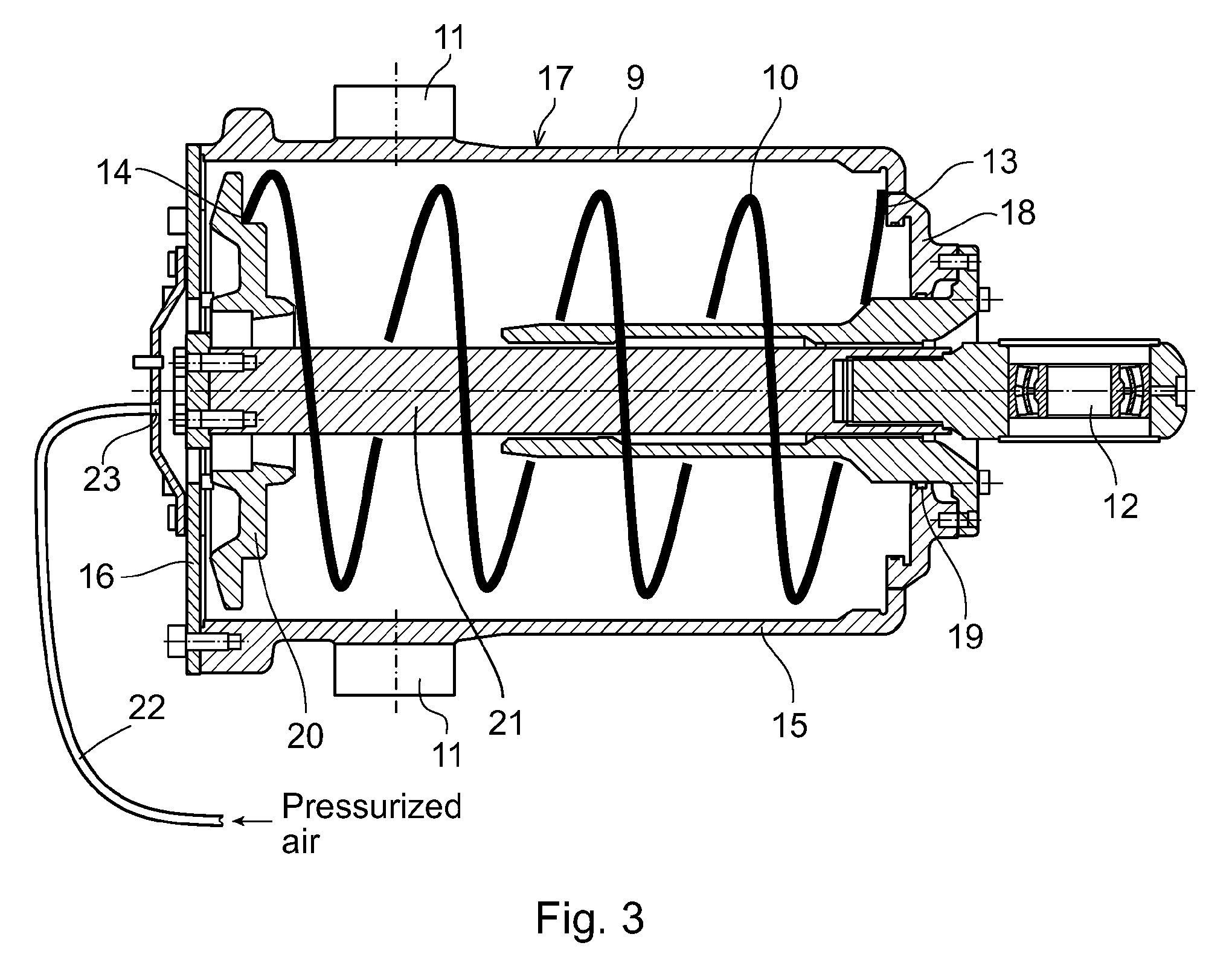
[0041]A balancing device 8 is mounted on the robot 1 (FIG. 3) and comprises a balancing cylinder 9, a piston 20, elastic spring means 10 and a pull rod 21. The cylinder 9 comprises a cylindrical body 17 mounted oscillating about an axis perpendicular to the axis of the cylinder. The piston 20 is mounted and adapted to slide in the cylindrical body 17 and is recalled towards an end position by the elastic spring means 10 arranged inside the cylinder. The pull...


PUM


Abstract

An industrial robot including a first robot part and a second robot part arranged to be moved in relation to each other. A balancing device is arranged between the first robot part and the second robot part. The balancing device is arranged to counteract a gravitational force upon relative movement of the robot parts. The balancing device includes a mechanical spring and a spring housing arranged enclosing the spring. The spring housing includes at least one air inlet adapted for pressurized air supply.

Description

TECHNICAL FIELD[0001]The present invention relates to an industrial robot comprising a balancing device with a mechanical spring means.BACKGROUND OF THE INVENTION[0002]Industrial robots usually comprise a robot foot, a stand and a robot arm. The stand is rotatably arranged on the robot foot. The robot arm is rotatably arranged in a joint on the stand. A six axis industrial robot, for example, comprises a first robot arm, a second robot arm, a wrist arranged with a tool holder and drive means comprising an electrical motor and a reduction gear rotation of each axis.[0003]In its initial position, which may also be a rest position, the robot is oriented with the first arm approximately vertical. When the robot is moving / operating, the first arm is rotated in relation to the stand while at the same time the first and second arm rotate in relation to each other. The total moving mass consists of the handling weight applied to the wrist as well as the actual dead weight of the robot. Upon...

Claims


Application Information

Patent Timeline
IPC IPC(8): B25J19/00
CPCB25J19/0016Y10T74/20305B25J19/0079
Inventor BROBERG, ARNEERKKI, ROLAND
Owner ABB (SCHWEIZ) AG
Learn More