
Framework to Determine the Capacity of A Structure

Inactive Publication Date: 2010-02-18
MINNAAR KAREL +4
View PDF13 Cites 20 Cited by
  • Summary
  • Abstract
  • Description
  • Claims
  • Application Information

AI Technical Summary

Problems solved by technology

Generally, pipelines may be affected by various forces that damage or rupture the pipeline.
Placing pipelines in these regions presents challenges in pipeline strength and durability that were not previously addressed in conventional pipeline designs.
In these regions, pipelines may be subjected to large upheaval or subsidence ground movements that occur from the ground freezing / thawing and / or large horizontal ground movements that occur from earthquake events.
Because of the ground movements, pipelines, which may be above or below ground, are subject to large strains and plastic deformations that may lead to compromising the integrity or serviceability of these pipelines, which may disrupt the flow of fluids.
In addition, because the pipe segments are typically welded together, the weld joints between the pipe segments or between the pipe segments and auxiliary components, such as elbows or flanges, may provide weak points that are susceptible to these forces.
For instance, a weld joint between two pipe segments may have flaws that weaken the pipeline.
If the weld joint has flaws, then the pipeline may fail at the weld joint due to imposed load conditions or ground movements.
There exists no generally accepted method to design a welded pipeline to sustain large plastic deformations associated with design methods such as strain-based design methods.
In some cases, even two-parameter theories become invalid under large strains.
In addition, the fracture parameter known to those skilled in the art as the J-integral is not a proven fracture parameter under the conditions of large scale plasticity or after significant crack growth.
Therefore, known fracture mechanics methods cannot be reliably applied to assess tensile capacity at strains beyond the yield point of the material.
Due to the lack of reliable predictive methods to determine the tensile capacity of welded pipelines, extensive proof testing is typically required to validate the tensile strain capacity of a pipeline.
Such a proof testing approach is an expensive and time-consuming methodology to develop an acceptable strain based design and typically impacts pipeline project schedules and cost.

Method used


Image

  • Framework to Determine the Capacity of A Structure
  • Framework to Determine the Capacity of A Structure
  • Framework to Determine the Capacity of A Structure

Examples


Embodiment Construction

[0032]In the following detailed description, the specific embodiments of the present invention will be described in connection with its preferred embodiments. However, to the extent that the following description is specific to a particular embodiment or a particular use of the present invention, this is intended to be illustrative only and merely provides a concise description of the exemplary embodiments. Accordingly, the invention is not limited to the specific embodiments described below, but rather, the invention includes all alternatives, modifications, and equivalents falling within the true scope of the appended claims.

[0033]The term “capacity” as used herein, refers to a physical quantity defining the maximum load, deformation, stress, strain, pressure, or temperature of a physical member before failure of that member. For example, a particular type of capacity is the “strain capacity,” which may be defined as the strain at which stable ductile tearing initiates or the stra...


PUM


Abstract

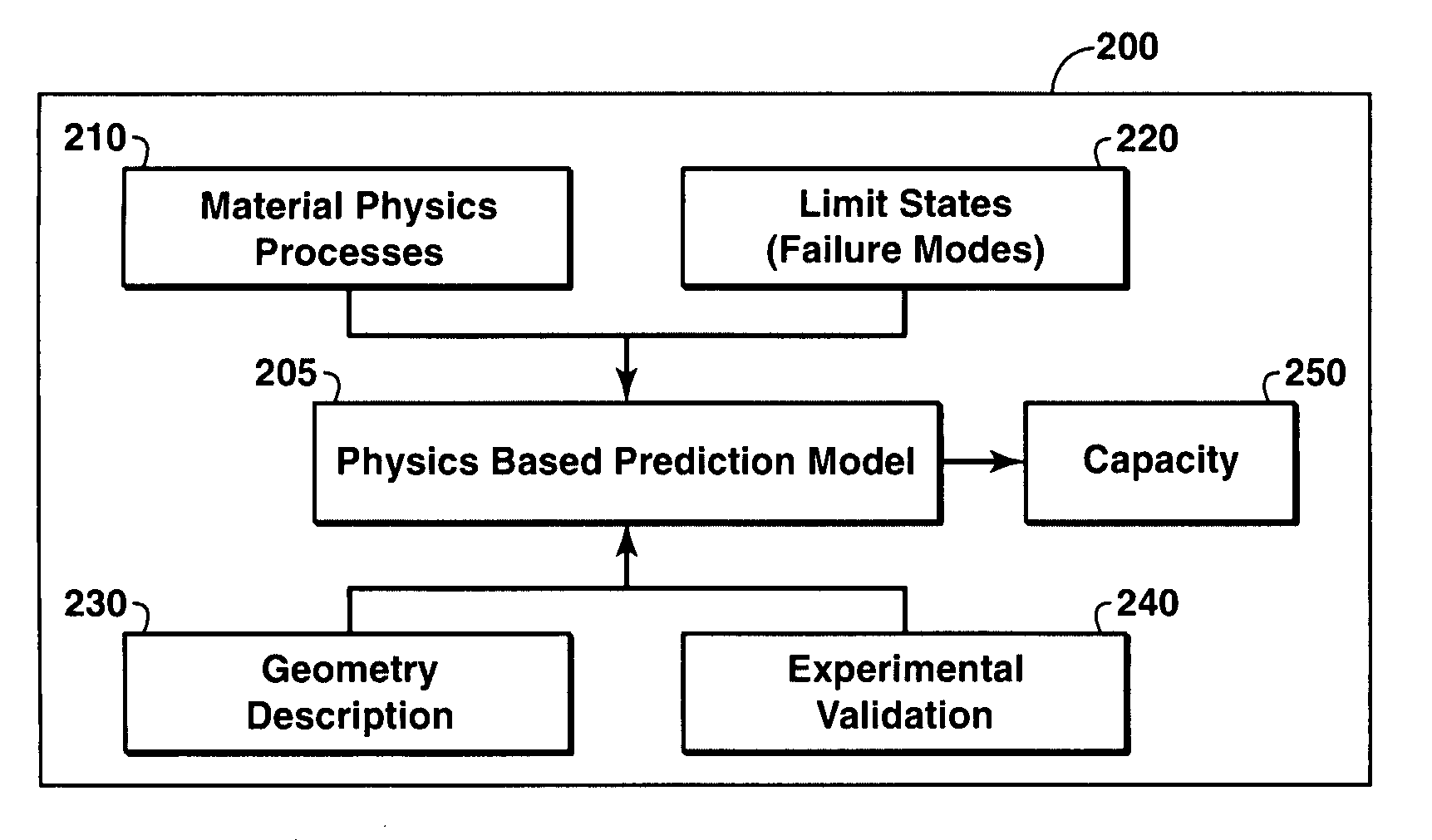
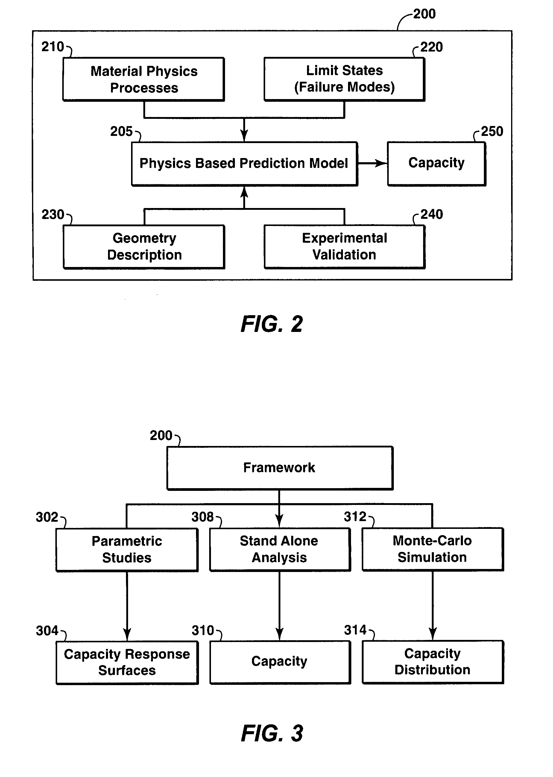
A framework for determining or predicting the capacity of a structure. The framework includes predicting the capacity of the structure utilizing a physics-based prediction model. The prediction model may be constructed from a variety of numerical analysis approaches. The prediction model further incorporates at least one material physics process, at least one geometry description, and at least one limit state. The limit states may include collapse, tensile fracture, and buckling. The framework calls for validation of the predicted capacity of the structure via experimental verification or other methods. In some embodiments, the structure is a pipeline for producing hydrocarbons and the modes of operation may include parametric studies, Monte-Carlo type distributions, or stand-alone values.

Description

CROSS REFERENCE TO RELATED APPLICATIONS[0001]This application claims the benefit of U.S. Provisional Application No. 60 / 919,053, filed Mar. 20, 2007.[0002]This application is related to U.S. Provisional Application No. 60 / 918,999 titled “Method to Measure Tearing Resistance,” filed Mar. 20, 2007.FIELD OF THE INVENTION[0003]The present invention relates to determining or predicting the capacity of structures. More particularly, the present invention relates to apparatuses and methods to measure and predict strain capacity of a welded structure, such as a pipeline having a flaw, utilizing a framework based on a physics-based prediction model.BACKGROUND[0004]This section is intended to introduce the reader to various aspects of art, which may be associated with exemplary embodiments of the present invention, which is described and / or claimed below. This discussion is believed to be helpful in providing the reader with information to facilitate a better understanding of particular aspec...

Claims


Application Information

Patent Timeline
IPC IPC(8): G06F17/50G06F17/10G06G7/50
CPCG06F2217/34G06F17/5018G06F2113/14G06F30/23
Inventor MINNAAR, KARELGIOIELLI, PAULO C.MACIA, MARIO L.RAHUL, PAKALBARDI, FRANCOIS C.
Owner MINNAAR KAREL
Learn More