Eureka AIR delivers breakthrough ideas for toughest innovation challenges, trusted by R&D personnel around the world.

Configuration of a process control system

Active Publication Date: 2010-02-18
HITACHI ENERGY SWITZERLAND AG
View PDF10 Cites 72 Cited by
  • Summary
  • Abstract
  • Description
  • Claims
  • Application Information

AI Technical Summary

Benefits of technology

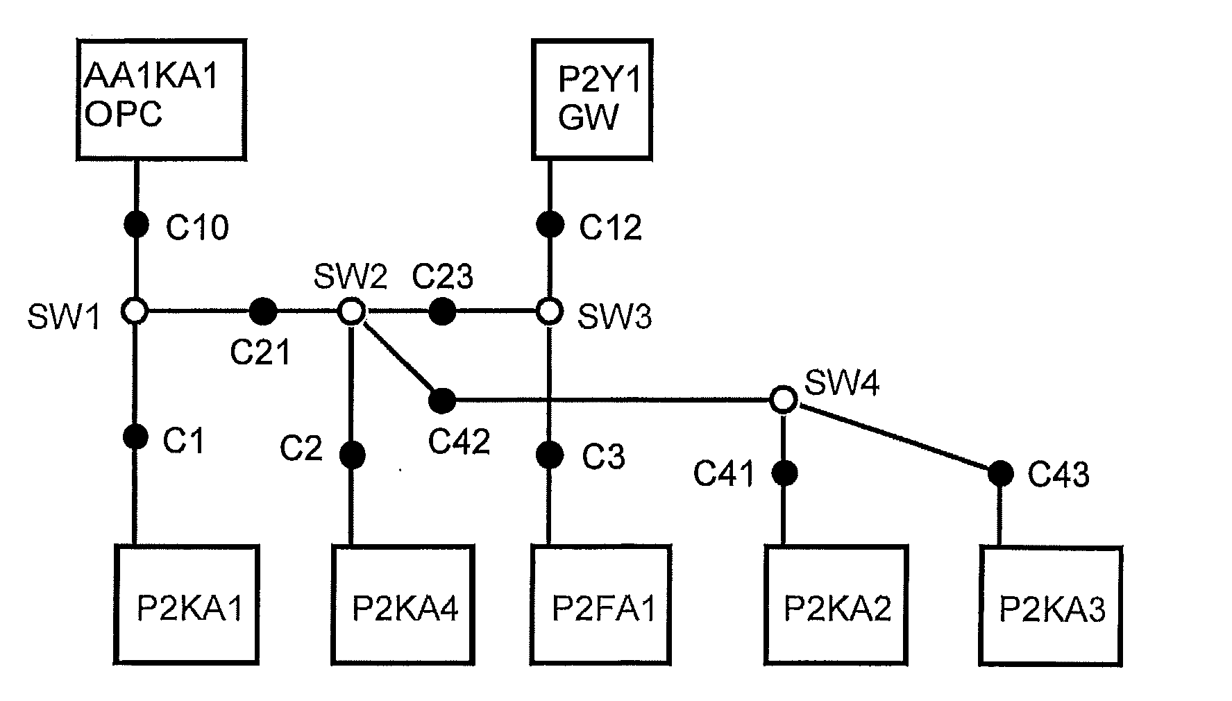
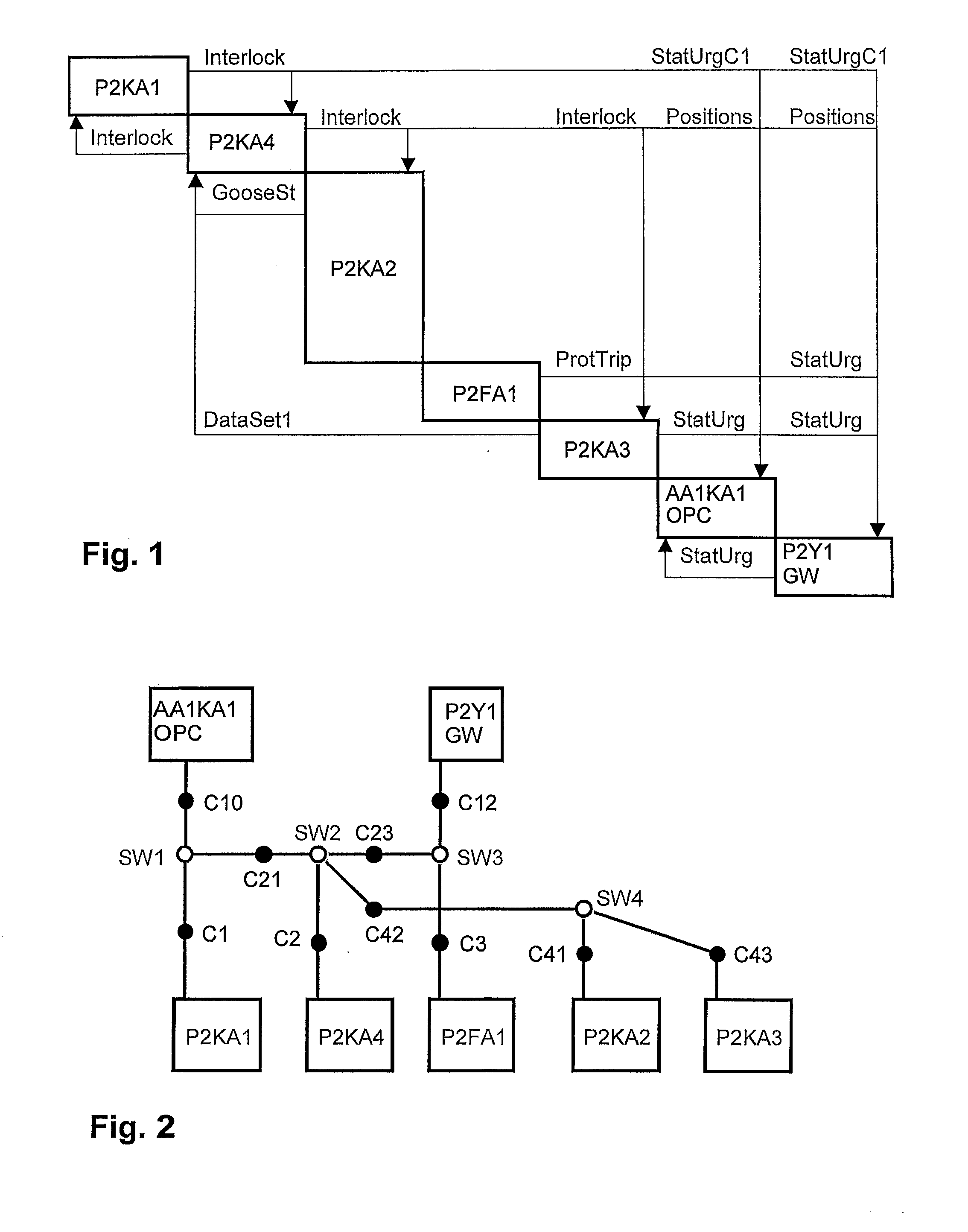
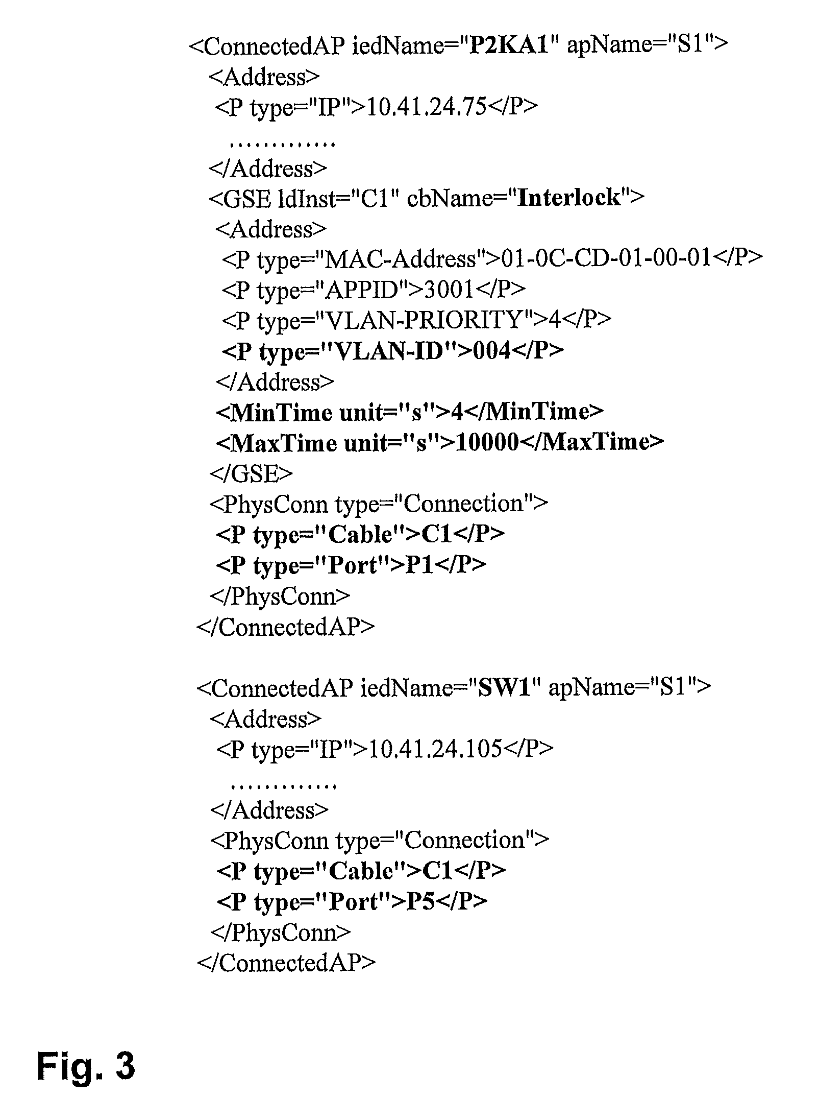
[0012]An exemplary embodiment provides a method of configuring a process control (PC) system with a plurality of intelligent electronic devices (IEDs) connected to at least one switch of an Ethernet switch-based communication network. A sender IED can be configured to send different messages to different predetermined receiver IEDs, and a switch of the communication network can be configured to forward periodic multicast messages irrespective of the receiver IEDs. The exemplary method comprises retrieving, for a sender IED among the plurality of IEDs and for each message configured to be transmitted by the sender IED, from a standardized configuration representation of the PC system having logical data flow definitions, receiver IEDs for which the message is destined, and a Virtual Local Area Network Identifier (VLAN ID). In addition, the method comprises assigning, for a receiver IED, a respective VLAN ID of each message destined for the receiver IED to an edge port of a switch of the communication network to which the receiver IED is connected.
[0013]An exempl

Problems solved by technology

However, the latter mechanism is disadvantageous because the central table has to be modified when replacing a failed terminal by a new one with a different MAC address, or because the address server containing this relation fails.
This can complicate the configuration of VLANs on the switches.
Furthermore, the assumption of all IEDs spontaneously sending data within their VLAN is normally not applicable for SA real time applications containing pure message receivers for certain VLANs.
Both these facts prohibit automatic VLAN detection by the switches based on received messages.
In addition, station level IEDs such as operator work station and gateway, may not be adapted to handle more than 200 to 1000 messages per second.

Method used


Image

  • Configuration of a process control system
  • Configuration of a process control system
  • Configuration of a process control system

Examples


Embodiment Construction

[0018]Exemplary embodiments as disclosed herein are directed to reducing network traffic and preventing overflow in switched communication networks of process control (PC) or substation automation (SA) systems through selective forwarding of messages to their intended destination. A method of configuring a PC or SA system and a configuration tool are disclosed herein.

[0019]According to an exemplary embodiment of the present disclosure, Virtual Local Area Network (VLAN) configuration data can be automatically generated from a logical data flow between intelligent electronic devices (IEDs) of the PC or SA system as described within the standardized configuration representation of the system. The process IEDs, as well as the switches of the Ethernet switch-based communication network to which the IEDs are connected, can be made aware of the assigned VLANs. Any performance analysis or diagnosis on these devices can show design problems with VLANs and communication architecture already a...


PUM


Abstract

Exemplary embodiments of the present disclosure automatically generate Virtual Local Area Network (VLAN) configuration data from a logical data flow between intelligent electronic devices (IEDs) of a process control (PC) system in accordance with a standardized configuration representation of the system. The process IEDs, switches of an Ethernet switch-based communication network to which the IEDs are connected, and connecting cables are made aware of the assigned VLANs. Any performance analysis or diagnosis on these components can show design problems with VLANs and communication architecture already at engineering or communication system design time.

Description

RELATED APPLICATION[0001]This application claims priority under 35 U.S.C. §119 to European Patent Application No. 08105067.6 filed in Europe on Aug. 18, 2008, the entire content of which is hereby incorporated by reference in its entirety.FIELD[0002]The present disclosure relates to process control systems, such as substation automation systems, for example.BACKGROUND INFORMATION[0003]Substations in high and medium-voltage power networks include primary devices such as electrical cables, lines, bus bars, switches, power transformers and instrument transformers, which can be arranged in switch yards and / or bays. These primary devices are operated in an automated way via a substation automation (SA) system. The SA system includes secondary devices, so-called intelligent electronic devices (IED), which are responsible for protection, control and monitoring of the primary devices. The IEDs may be assigned to hierarchical levels, i.e. the station level, the bay level, and the process lev...

Claims


Application Information

Patent Timeline
IPC IPC(8): H04L12/56
CPCH04L12/4641H04L41/08Y04S40/162H04L41/0879H04L41/0886H04L41/0843Y04S40/00H04L41/0895
Inventor WIMMER, WOLFGANG
Owner HITACHI ENERGY SWITZERLAND AG
Why Eureka
Eureka Blog
Learn More