Valve Gear

Active Publication Date: 2010-02-11
MITSUBISHI POWER LTD
View PDF13 Cites 4 Cited by
  • Summary
  • Abstract
  • Description
  • Claims
  • Application Information

AI Technical Summary

Benefits of technology

[0009]For the purpose of achieving such an object as described above, the present inventors conceived the idea that the corrosion due to a potential difference is prevented by forming the whole of a valve stem and a valve bush from a Ni-based superalloy and the corrosion occurrence is reduced by forming the valve bush from a cast part that easily absorbs microvibrations. That is, the valve gear of the present invention comprises a valve stem and a valve bush that slidably supports the valve stem, and is characterized in that the valve stem is formed from a forged part made of a Ni-based superalloy, and that the valve bush is formed from a cast part made of a Ni-based superalloy.

Problems solved by technology

Consequently, the sticking of the valve stem is caused as the case may be.
Therefore, the steam amount leaking from the portion surrounding the valve stem is increased to cause problems such as the decrease of the thermal efficiency of a whole plant.

Method used


Image

  • Valve Gear
  • Valve Gear
  • Valve Gear

Examples


example

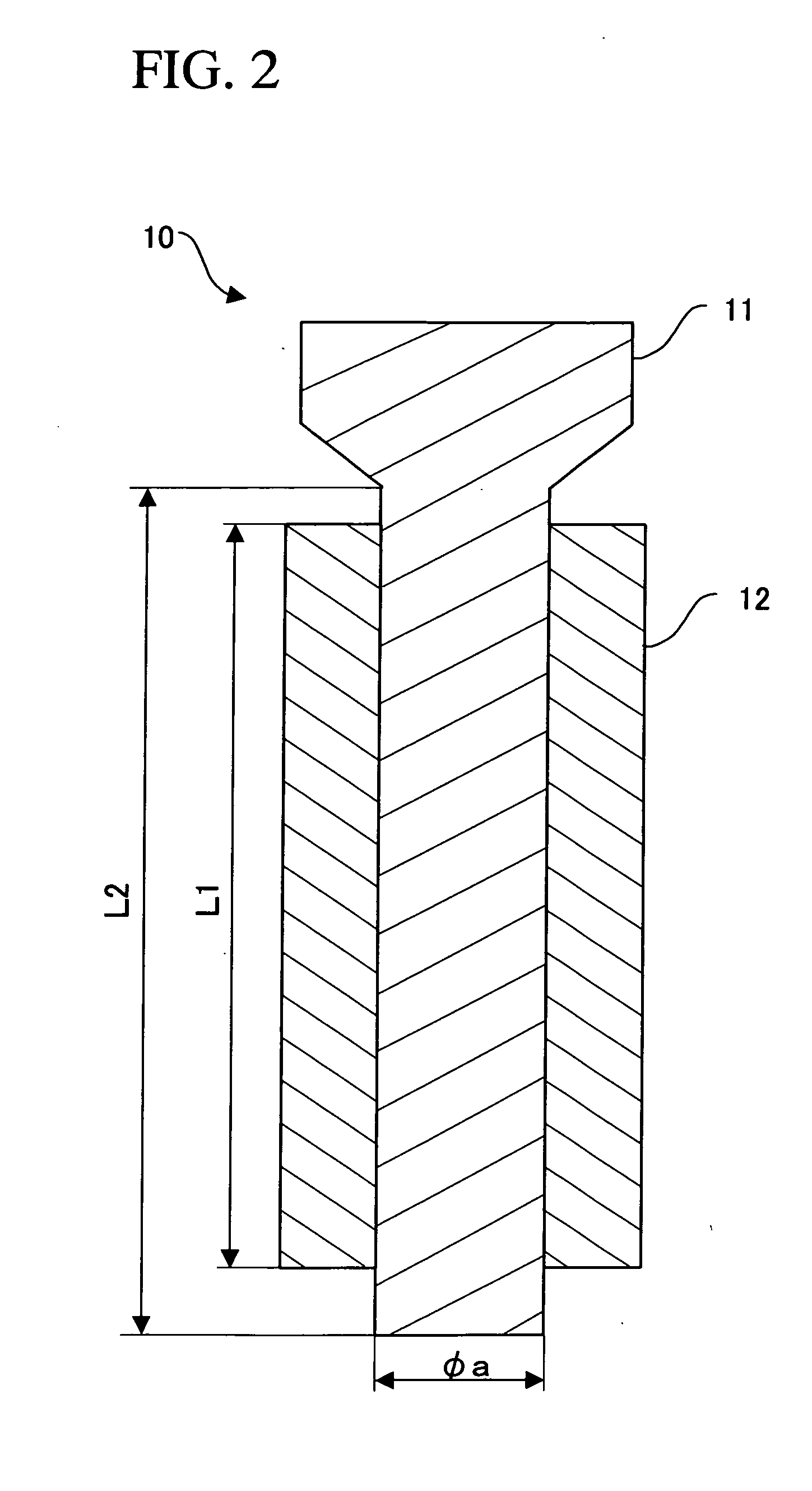
[0032]A test member 10 shown in FIG. 2 was prepared. A high-temperature corrosion test was conducted by subjecting this test member 10 to an environment in which high-temperature steam (approximately 593° C.) flows. This test member 10 is composed of a simulated valve stem 11 corresponding to the valve stem 6 shown in FIG. 1 and a simulated valve bush 12 corresponding to the valve bush 7 shown in FIG. 1. Incidentally, in FIG. 2, φa=20 mm, L1=90 mm, L2=100 mm. The clearance between the outer diameter of the simulated valve stem 11 and the simulated valve bush 12 was set at 0.02 mm.

[0033]The following four test members 10 were prepared by changing materials for the simulated valve stem 11 and the simulated valve bush 12.[0034]No. 1 Simulated valve stem 11: a forged part made of NCF718 (the composition of NCF718 is shown below; ditto for the following)[0035]Simulated valve bush 12: a cast part made of NCF718[0036]No. 2 Simulated valve stem 11: a forged part made of NCF718[0037]Simulate...


PUM


Abstract

Provided is a valve gear in which corrosion due to a potential difference does not occur and which can reduce the corrosion occurrence even when loads due to microvibrations are given. The valve gear according to the present invention comprises a valve stem 6 and a valve bush 7 that slidably supports the valve stem 6. The valve stem 6 is formed from a forged part made of a Ni-based superalloy and the valve bush 7 is formed from a cast part made of a Ni-based superalloy. The preferable surface roughness of a sliding surface of the valve stem 6 in contact with the valve bush 7 and the preferable surface roughness of a sliding surface of the valve bush 7 in contact with the valve stem 6 is 100 μm or less in units of Rz.

Description

TECHNICAL FIELD[0001]The present invention relates to a valve gear and, in particular, to a valve gear capable of preventing the sticking between the valve stem of a steam valve and a valve bush supporting the valve stem.BACKGROUND ART[0002]A main steam valve in a steam turbine is used under harsh conditions of high temperature and high pressure, and further takes a task of controlling high-speed steam flow. Under high temperature, the surface of a metal is in an activated state to react with the high-temperature steam present in the atmosphere to produce an oxide film. This oxide film has different adhesion strength to the base metal, depending on the composition of the base metal and the atmospheric conditions, and undergoes delamination at every repeated opening-closing movement of the valve. The delaminated matter is deposited locally in the recessed portions of the valve stem by the sliding of the valve stem so as to fill in the clearance between the valve bush and the valve st...

Claims


Application Information

Patent Timeline
IPC IPC(8): F16K25/00
CPCF16K27/02F16K1/32
Inventor TAKEI, MAONISHIMURA, TOSHINARI
Owner MITSUBISHI POWER LTD
Why Eureka
Try Eureka