
Loading dock leveler with lip extension mechanism

a technology of extension mechanism and loading dock, which is applied in the direction of loading/unloading, bridges, constructions, etc., can solve the problems of loss of effective power, difficulty in walking the unit down, and difficulty in extending and holding the lip in position

Active Publication Date: 2010-02-11
NORDOCK
View PDF21 Cites 12 Cited by
  • Summary
  • Abstract
  • Description
  • Claims
  • Application Information

AI Technical Summary

Benefits of technology

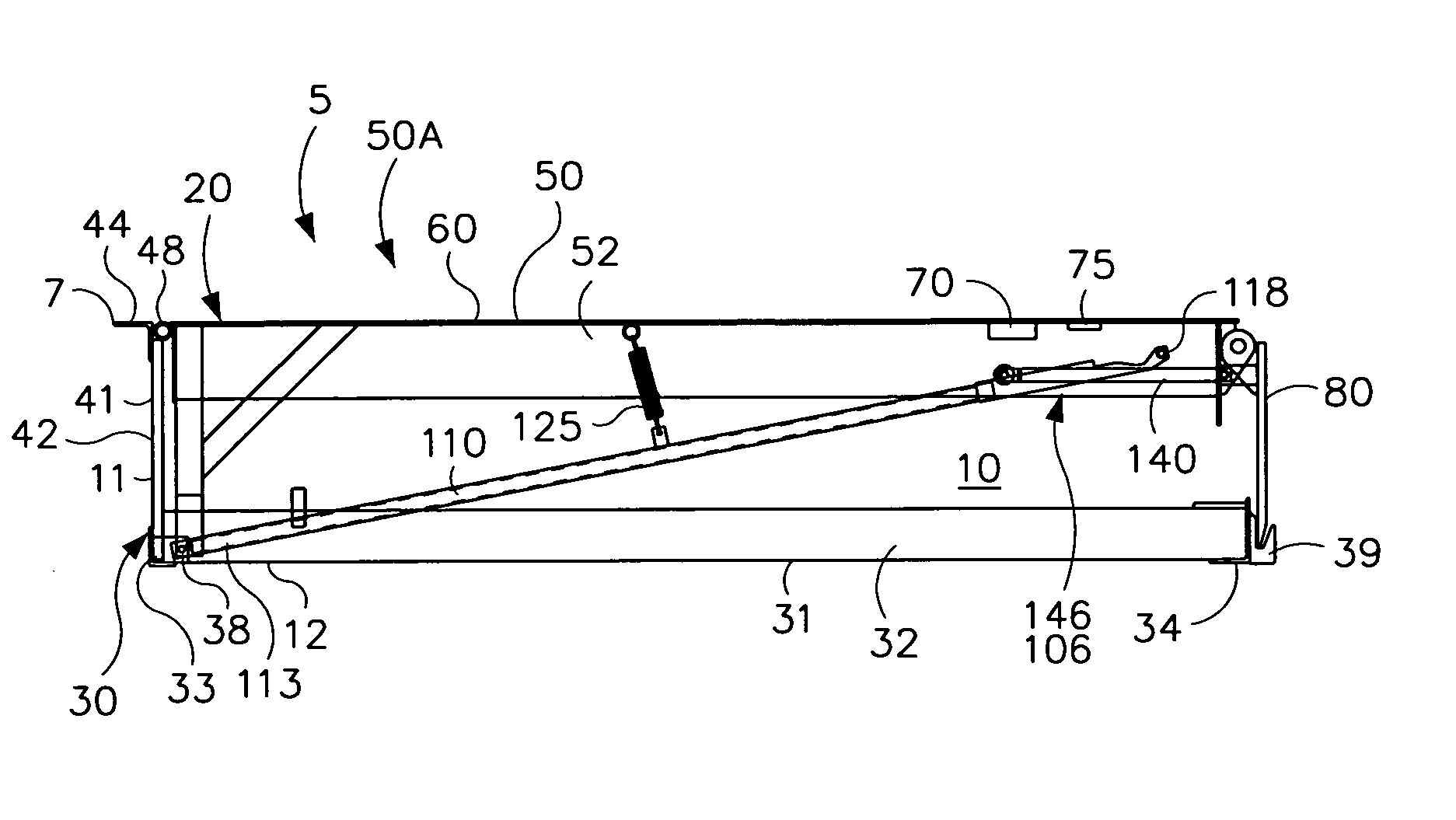
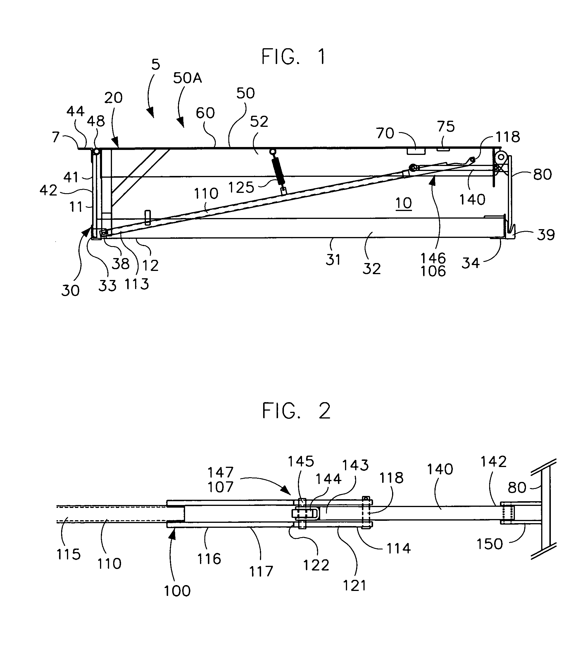
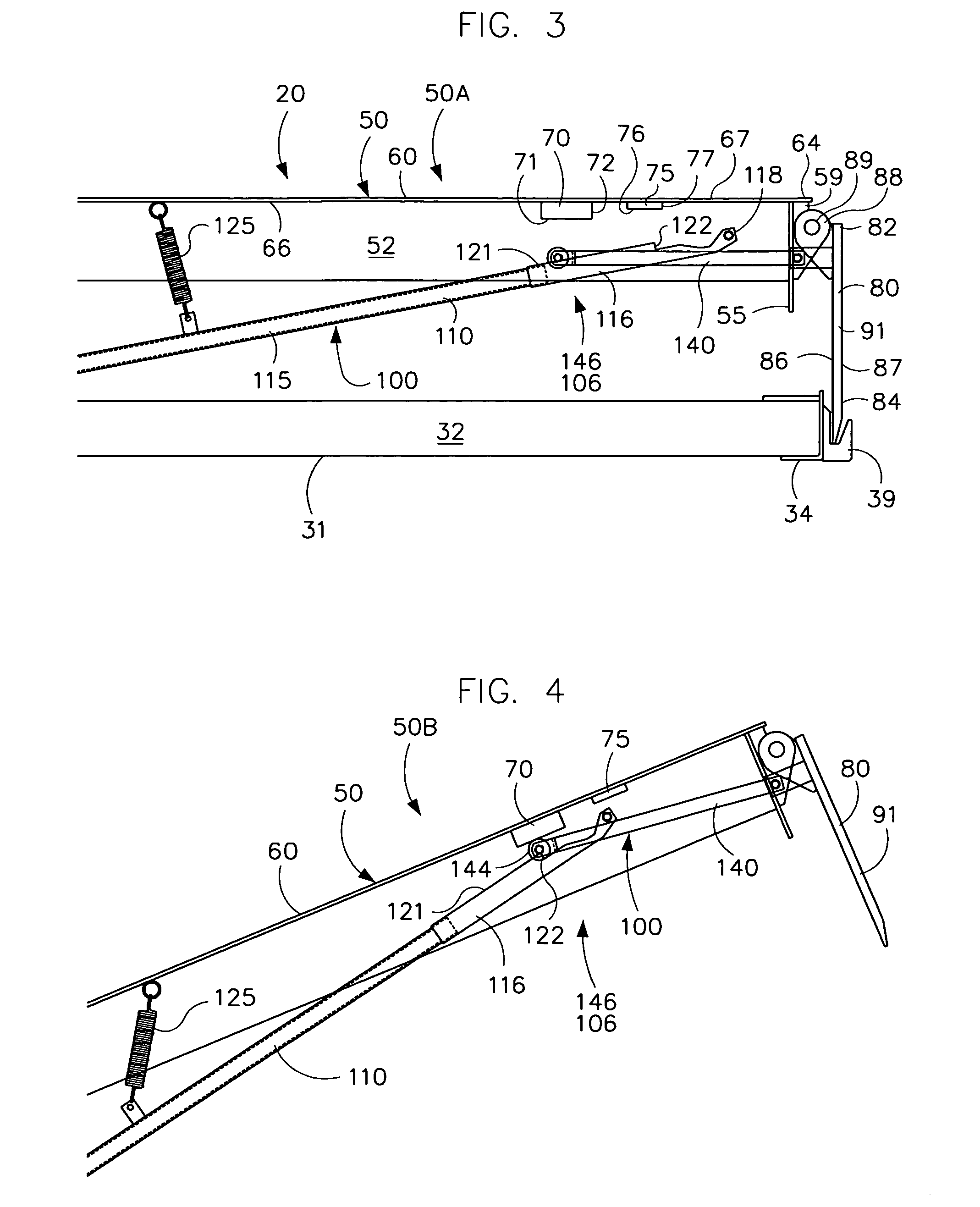
[0011]An advantage of the present dock leveler is the power of its lip extension mechanism. The extension mechanism can easily extend and hold the heavier, more durable lips in use today. The lip is extended by substantially linearly aligned rigid metal drive components that engage when the deck is raised to a predetermined inclined position. Although a spring helps align these components, the spring does not generate the force to extend the lip. This power of the extension mechanism remains relatively constant as the lip is extended, including at the start of the lip extension when that power is needed most.
[0012]Another advantage of the present dock leveler is the inventive geometric arrangement of its components to create differing relative motions and the use of gravity to engage and disengage the lip extension mechanism. The geometric configuration of the components and use of gravity also transition the lip extension mechanism into a locking mechanism. This transition automatically occurs as the lip reaches its fully extended position, and the locking mechanism simultaneously engages to lock and hold the lip in its fully extended position as the deck continues to be lowered into engagement with the truck trailer. The engagement with the truck trailer automatically disengages or unlocks the locking mechanism so that the lip will return to its pendant position under its own weight. Maintenance requirements are reduced as the rigid metal drive components are not prone to fail due to wear, environmental considerations, a lack of lubrication or spring fatigue. Springs, mechanical latches, dampers and the like are not used to hold the lip in its extended position.
[0013]A further advantage of the present dock leveler is its reduced number of components. The same components that combine to extend the lip are used to form the locking mechanism that holds the lip extended, and allows the locking mechanism to release when the lip engages the truck trailer. Its geometric design and relatively few components decrease manufacture, assembly and maintain costs. This design also allows the compact leveler to move through a wide range of motion.

Problems solved by technology

A problem with conventional dock levelers is that the wider, longer or thicker the lip, the harder it is to extend and hold the lip in position.
This loss of effective power occurs at the start of its extension, when the assist spring is needed most.
Yet, increasing the tension or force of the assist springs makes it harder to walk the unit down.
Another problem with conventional dock levelers is that they tend to lose their ability to fully extend their lip.
The lip extension mechanism begins to fail due to wear and other environmental considerations, a lack of lubrication or spring fatigue.
Even a short outage can be significant given that these devices typically operate in a heavy industrial context.
Still, hydraulic dampers have two significant drawbacks.
Second, the viscosity of the hydraulic fluid is sensitive to changes in temperature.
In cold temperatures, the lip falls too slowly when the leveler is removed from the truck.
A further problem with conventional dock levelers is that the lip extension mechanism is complex and includes many components.
These mechanisms and their various components increase the cost to manufacture, assemble and maintain the machine.
These various mechanisms and components also tend to decrease the range of motion of the leveler.
The leveler cannot be raised or lowered beyond certain upper and lower limits because of the tight or cramped arrangement of the many moving parts.

Method used


Image

  • Loading dock leveler with lip extension mechanism
  • Loading dock leveler with lip extension mechanism
  • Loading dock leveler with lip extension mechanism

Examples


Embodiment Construction

[0041]While this invention is susceptible of embodiments in many different forms, the drawings show and the specification describes in detail preferred embodiments of the invention. It should be understood that the drawings and specification are to be considered an exemplification of the principles of the invention. They are not intended to limit the broad aspects of the invention to the embodiments illustrated.

[0042]Loading docks 5 have generally flat, horizontal, elevated floor surface 7 and a generally vertical front wall. The loading dock 5 has a pit 10 of sufficient depth to house a dock leveler as shown in FIG. 1. The pit 10 has a rear wall or surface 11, a bottom floor or surface 12, opposed sidewalls or surfaces, and an open front. The floor 12 of the pit 10 is generally horizontal or slightly sloped for drainage, and is spaced a desired distance from the floor 7 of the loading dock 5. The walls 11 are generally vertical and normal to floor surfaces 7 and 12. The loading doc...


PUM


Abstract

A dock leveler with a deck and an extendable lip that hangs pendant when the deck is in a stored position. A lip extension mechanism engages when the deck is raised to a raised or cocked position. As the deck is lowered to an intermediate transition position, the extension mechanism extends the lip to a fully extended position. At the transition position, the lip extension mechanism automatically disengages and a lip locking mechanism automatically and simultaneously locks and holds the lip in its fully extended position. When the deck is further lowered so that the lip comes to rest on a truck trailer, the locking mechanism automatically released or unlocked. The lip returns to its pendant position when the deck is raised from the truck bed. After the truck pulls away from the dock, the deck is lowered to its stored position.

Description

TECHNICAL FIELD OF THE INVENTION[0001]This invention relates to a loading dock leveler with cooperating lip extension and lip locking mechanisms that extend, hold and release its lip during operation.BACKGROUND OF THE INVENTION[0002]This application seeks priority on U.S. Provisional Application No. 61 / 188,354 filed Aug. 8, 2008.[0003]Dock levelers are used to transfer goods between a building and a truck trailer. Dock levelers bridge the gap between the building floor to the bed of the trailer or similar carrier. Dock levelers include a frame or support structure for mounting the leveler in a pit of a loading dock. The rear end of a conventional dock leveler is hinged to the building floor. The opposite end has an extendable lip plate that pivots out and onto the trailer bed. Levelers are adapted to move from a generally horizontal position where the upper surface of the deck is flush with the surface of the building floor to a second generally inclined position to provide a ramp b...

Claims


Application Information

Patent Timeline
IPC IPC(8): B65G69/34E01D1/00B65G69/28
CPCB65G69/2841B65G69/2823
Inventor GLEASON, DENISBARRETT, ANDREW
Owner NORDOCK
Learn More