
Ultrasonic Through-Wall Communication (UTWC) System

a technology of ultrasonic energy and transmission system, applied in transmission systems, sonic/ultrasonic/infrasonic transmission, instruments, etc., can solve problems such as difficult or impossible battery replacement, and achieve the effect of reducing the power requirements of the inside circui

Inactive Publication Date: 2010-02-04
THE UNITED STATES AS REPRESENTED BY THE DEPARTMENT OF ENERGY +1
View PDF13 Cites 355 Cited by
  • Summary
  • Abstract
  • Description
  • Claims
  • Application Information

AI Technical Summary

Benefits of technology

[0010]The system according to the present invention is characterized by minimal complexity on the inside of the pressure vessel, while still allowing for reliable communication at sufficient data rates. Also, the ability to deliver power to the inside electronics is desired, since the pressure vessel may be sealed for an extended period of time making battery replacement difficult or impossible.
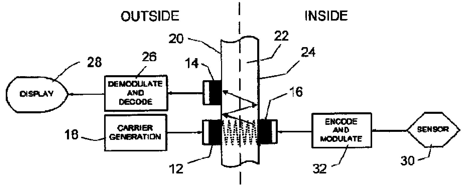
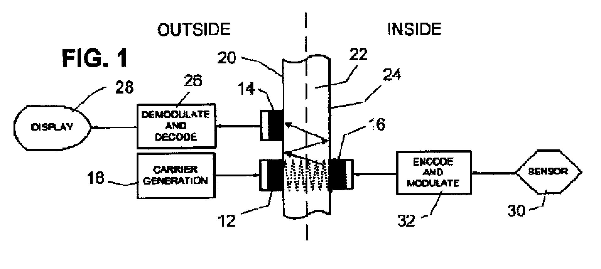
[0013]According to the present invention the carrier for the data transmission from inside the wall (e.g. a 1 MHz CW) is generated at the outside. Data is sent by varying the electrical load on the inside transducer which changes its acoustic impedance which, in turn, modulates the size of the reflected carrier signal. This change in the reflected carrier is detected at the outside transducer (either the transmitting transducer or a second outside transducer) to receive the data. This approach has the advantage over the prior art that the inside circuit does not need to include an oscillator nor does it need to supply power to the inside transducer. Thus simplicity is gained and lower power requirements for the inside circuit is achieved.

Problems solved by technology

Also, the ability to deliver power to the inside electronics is desired, since the pressure vessel may be sealed for an extended period of time making battery replacement difficult or impossible.

Method used


Image

  • Ultrasonic Through-Wall Communication (UTWC) System
  • Ultrasonic Through-Wall Communication (UTWC) System
  • Ultrasonic Through-Wall Communication (UTWC) System

Examples


Embodiment Construction

[0055]Referring now to the drawings, in which like reference numerals are used to refer to the same or similar elements, several transducer configurations with both the carrier generator and the receiver on the outside were investigated. In a three-transducer “hybrid approach” illustrated in FIG. 1, a transmitter 12 and a receiver 14 are adjacent one another and are acoustically coupled to an outside surface 20 of a solid (e.g. steel) wall 22. A modulating transducer 16 is acoustically coupled on the inside surface 24, directly across from, e.g. axially aligned with, the transmitting transducer 12. While axial alignment of the transducers is intended to optimize the fraction of the applied power that reaches the modulating transducer on the inside, it is not necessary to have such alignment. A continuous-wave (CW) or pulsed carrier signal generated by a carrier generator 18, is applied through the transmitter 12, travels through the wall channel, is amplitude (AM) modulated through ...


PUM


Abstract

Apparatus for communicating information across a solid wall has one or two outside ultrasonic transducers coupled to an outside surface of the wall and connected to a carrier generator for sending an ultrasonic carrier signal into the wall and for receiving an output information signal from the wall. One or two inside ultrasonic transducers are coupled to an inside surface of the wall and one of them introduces the output information signal into the wall. When there are two inside transducers inside the wall, one receives the carrier signal and the second transmits the carrier after it is modulated by the output information from the sensor. When there is one inside transducer, the output information from the sensor is transmitted by changing the reflected or returned signal from the inside transducer. A power harvesting circuit inside the wall harvests power from the carrier signal and uses it to power the sensor.

Description

CROSS-REFERENCE TO RELATED APPLICATIONS[0001]This application claims priority from U.S. Provisional Patent Applications 60 / 848,840 filed Oct. 2, 2006 and 60 / 947,714 filed Jul. 3, 2007, both of which are incorporated here by reference.STATEMENT OF GOVERNMENT INTEREST[0002]The Government has certain rights to this invention since it was created in part under a contract with the U.S. Department of Energy.FIELD AND BACKGROUND OF THE INVENTION[0003]The present invention relates generally to the field of communication and, in particular, to wireless communication using ultrasonic energy.[0004]There are presently no commercial products available that communicate digital information through a thick solid (e.g. steel) wall channel using ultrasonic techniques. In applications which require the use of a solid (e.g. steel) wall pressure vessel, it is often desirable to monitor the conditions inside the pressure vessel through the use of various sensors. The environment inside a pressure vessel ...

Claims


Application Information

Patent Timeline
Patent Type & Authority Applications(United States)
IPC IPC(8): H04B1/02
CPCH04B11/00G08C23/02
Inventor SAULNIER, GARYSCARTON, HENRYSHOUDY, DAVIDDAS, PANKAJGAVENS, ANDREW
Owner THE UNITED STATES AS REPRESENTED BY THE DEPARTMENT OF ENERGY
Learn More