
Lamp and lighting equipment

Inactive Publication Date: 2010-02-04
TOSHIBA LIGHTING & TECH CORP
View PDF11 Cites 106 Cited by
  • Summary
  • Abstract
  • Description
  • Claims
  • Application Information

AI Technical Summary

Benefits of technology

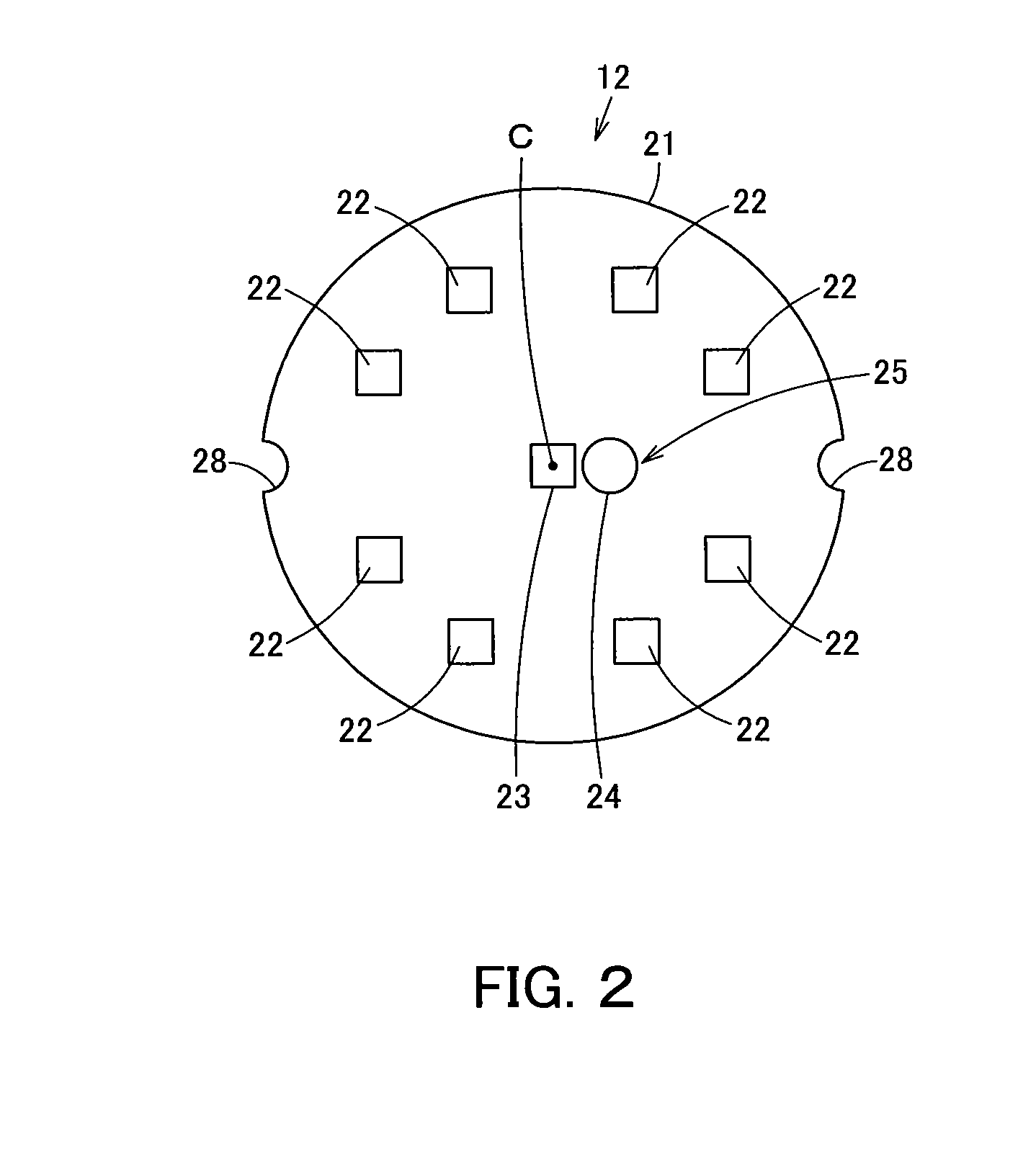
[0018]Then, the configuration that a plurality of light emitting elements are derived from the center position of one main surface of the element substrate main body to be provided onto an outer edge side and simultaneously at least a part of the connection receiving part, to which the connection part connected to a distal end of the power feeder from the lighting device can be connected, and the wiring part including the wiring hole which is adjacent to the connection receiving part and penetrating the element substrate main body and allows insertion of the power feeder of the lighting device, is positioned at a spot that overlaps the center position of the one surface side of the element substrate main body enables to insert the power feeding part into the wiring hole for easy connection between the connection part and the connection receiving part. Therefore, it becomes possible to keep the connection receiving part away from each of the light emitting elements approximately the same distance so that emitted light is not easily blocked and a decrease in uniformity of light distribution is suppressed while ease in assembly is ensured.
[0039]Then, by the lamp installed in the equipment main body, it becomes possible to configure lighting equipment which can suppress a decrease in light distribution uniformity while ensuring ease in assembly and can increase reliability.

Problems solved by technology

However, such a self-ballasted lamp has a problem that is decreased because the connector board blocks emission from the LED.

Method used


Image

  • Lamp and lighting equipment
  • Lamp and lighting equipment
  • Lamp and lighting equipment

Examples


Embodiment Construction

[0049]Hereinafter, embodiments of the present invention will be described with reference to the drawings.

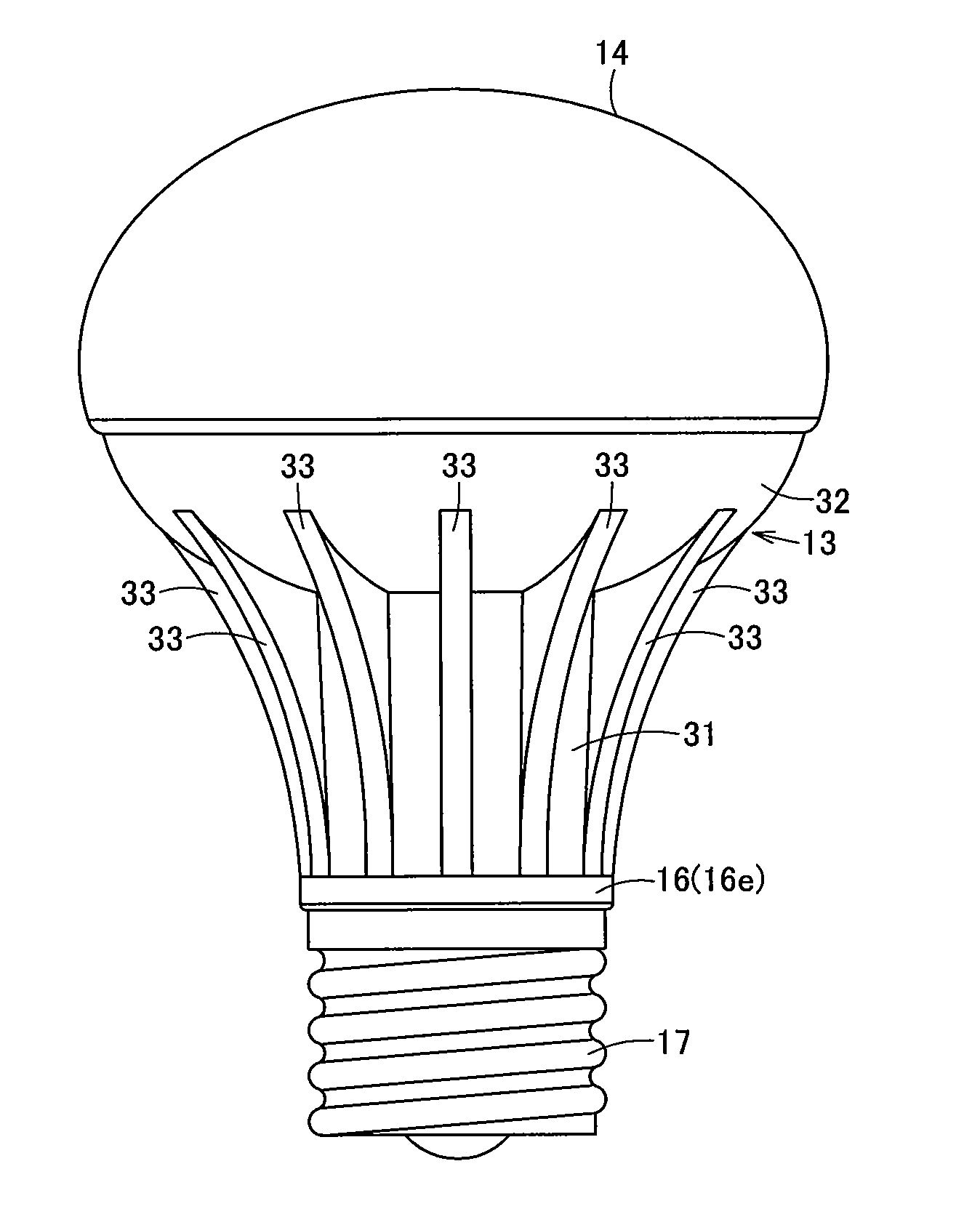
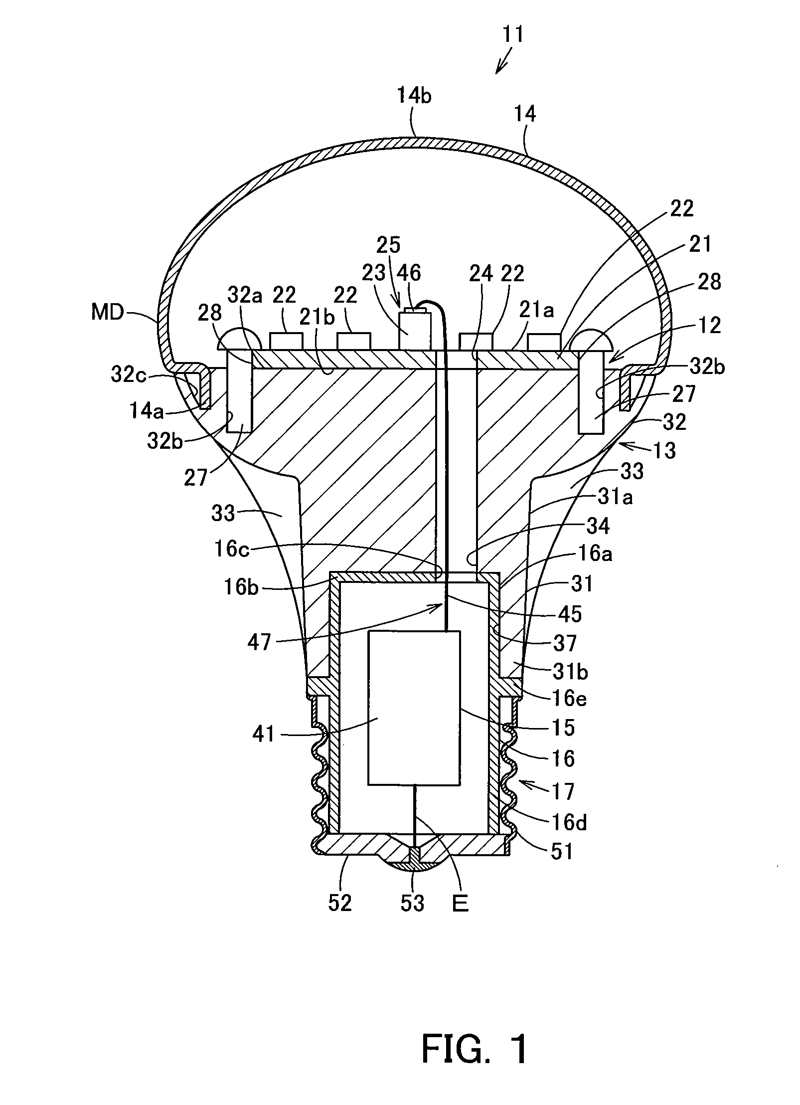
[0050]FIGS. 1 to 4 show an embodiment and FIG. 1 is a longitudinal-sectional view of a lamp, FIG. 2 is a plan view of an element substrate of the lamp, FIG. 3 is a side elevational view of the lamp, and FIG. 4 is an explanatory view schematically showing a condition where lighting equipment on which the lamp is mounted is installed on a ceiling surface.

[0051]In FIGS. 1 and 3, 11 is a self-ballasted LED lamp being a self-ballasted lamp as the lamp. The self-ballasted LED lamp 11 includes an LED substrate 12 which is an element substrate and is attached on one edge side of a radiator 13, a globe 14 which covers the LED substrate and is attached on the one edge side of the radiator 13, and a storage case 16 being an insulation case and storing a lighting circuit substrate 15 which is a lighting device, and a cap 17 is attached to the storage case 16. Moreover, the self-ballasted LED...


PUM

PropertyMeasurementUnit
Thermal conductivityaaaaaaaaaa

Abstract

A plurality of LEDs are provided to an outer edge side of a center position of one main surface of an LED substrate main body in a deviated manner respectively. The wiring part including the connector receiving part and the wiring hole are provided at a position that overlaps the center position of the one main surface side of the LED substrate main body. Since the power feeding part is inserted into the wiring hole, the connection part and the connector receiving part can be easily connected and therefore it becomes possible to ensure ease in assembly. Since the connector receiving part is kept away from each of the LEDs with substantially equal distance so that emitted light is hardly blocked, decrease in uniformity of light distribution can be suppressed.

Description

INCORPORATION BY REFERENCE[0001]The present invention claims priority under 35 U.S.C. §119 to Japanese Patent Application Nos. 2008-196678 and 2008-303794 filed on Jul. 30, 2008 and Nov. 28, 2008, respectively. The contents of these applications are incorporated herein by reference in their entirety.BACKGROUND OF THE RELATED ART[0002]1. Field of the Invention[0003]The present invention relates to a lamp and lighting equipment including an element substrate on which a plurality of light emitting elements are provided.[0004]2. Background of the Invention[0005]Conventionally, in an LED lamp which is a lamp using an LED as a light emitting element, an LED substrate which is an element substrate mounting LEDs equally on an outer circumference edge portion of the substrate is attached to one edge side of a heat radiation part and a globe is attached to the one edge side of the heat radiation part covering the LED substrate as shown in, for example, Japanese Laid-Open Patent Publication No...

Claims


Application Information

Patent Timeline
IPC IPC(8): H01J61/52
CPCF21Y2101/02F21K9/1355F21V3/02F21V3/0427F21V3/0445F21V29/89F21V23/006F21V19/0055F21V29/773F21V29/87F21V23/002F21V29/508F21K9/23F21Y2115/10F21K9/238F21V3/0615F21V3/0625
Inventor TANAKA, TOSHIYAHISAYASU, TAKESHIOSAWA, SHIGERU
Owner TOSHIBA LIGHTING & TECH CORP
Learn More