
Spinous process fixated bilateral drilling guide

a technology of fixation guide and spinous process, which is applied in the field of drilling guide, can solve the problems of not being useful for fixation to a spinous process, not allowing for adjustment of drilling path in the lateral plane of the vertebra,

Inactive Publication Date: 2010-01-28
ALPHA GUIDE HLDG LLC
View PDF5 Cites 60 Cited by
  • Summary
  • Abstract
  • Description
  • Claims
  • Application Information

AI Technical Summary

Benefits of technology

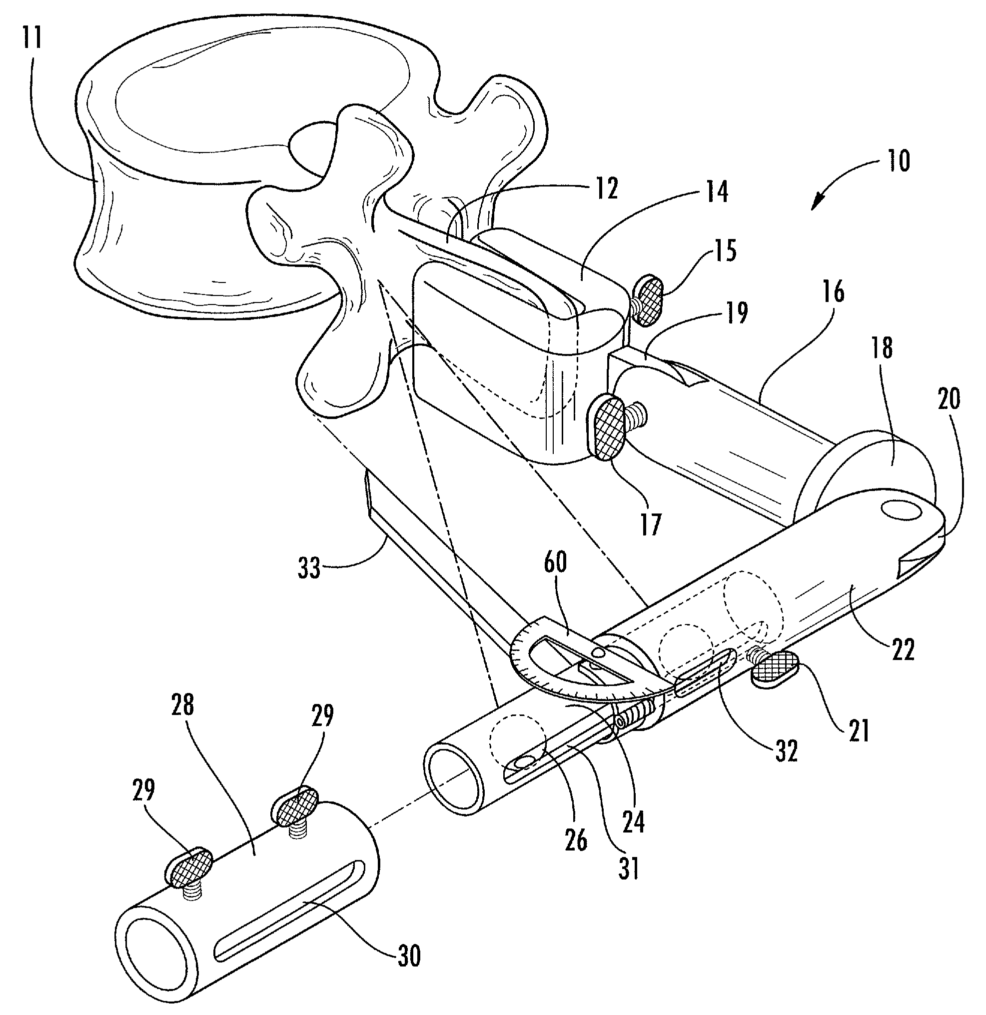
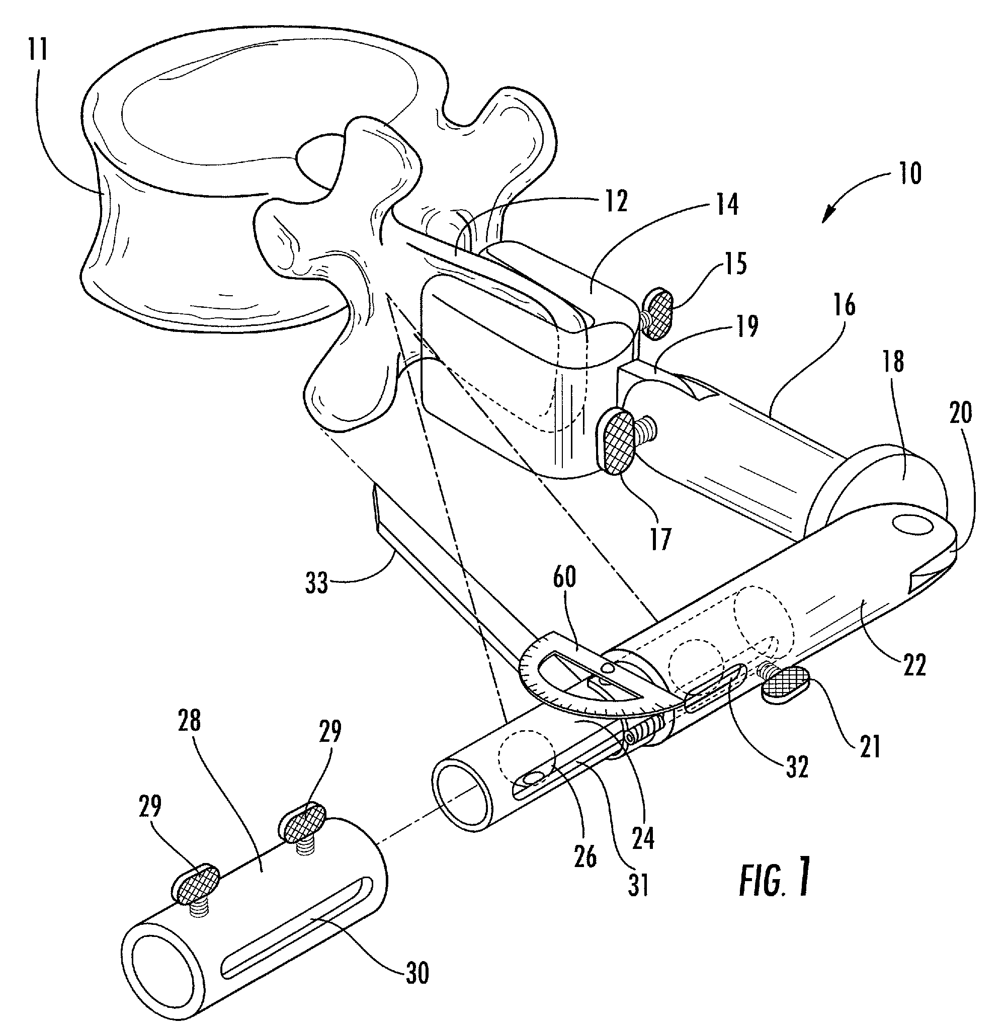
[0013]In accordance with the present invention there is provided a bilateral drilling and screw placement guide adapted for fixation to the spinous process of a vertebral body. The positioning and surgical guiding instrument is adapted for use in conjunction with a drilling tool. The guide includes an engagement device for attachment to a region of the spinous process, to which an adjustably attached support member is affixed. This allows for immobilizing the guide upon the spinous process anatomical landmark, in a specific orientation with respect thereto. The guide includes a bilaterally adjustable drill guide assembly for precise anatomical positioning of the drill and screw placement guides bilaterally about the sagittal and coronal planes so as to enable the defining of a plurality of drilling axes extending toward the vertebral body. The device further provides for adjustment to account for anatomical variations in width along the axial plane, and includes pointing and angular positioning functionality which provides for repeatable and reliable pilot hole and screw placement along a plurality of angles about the sagittal and coronal planes.
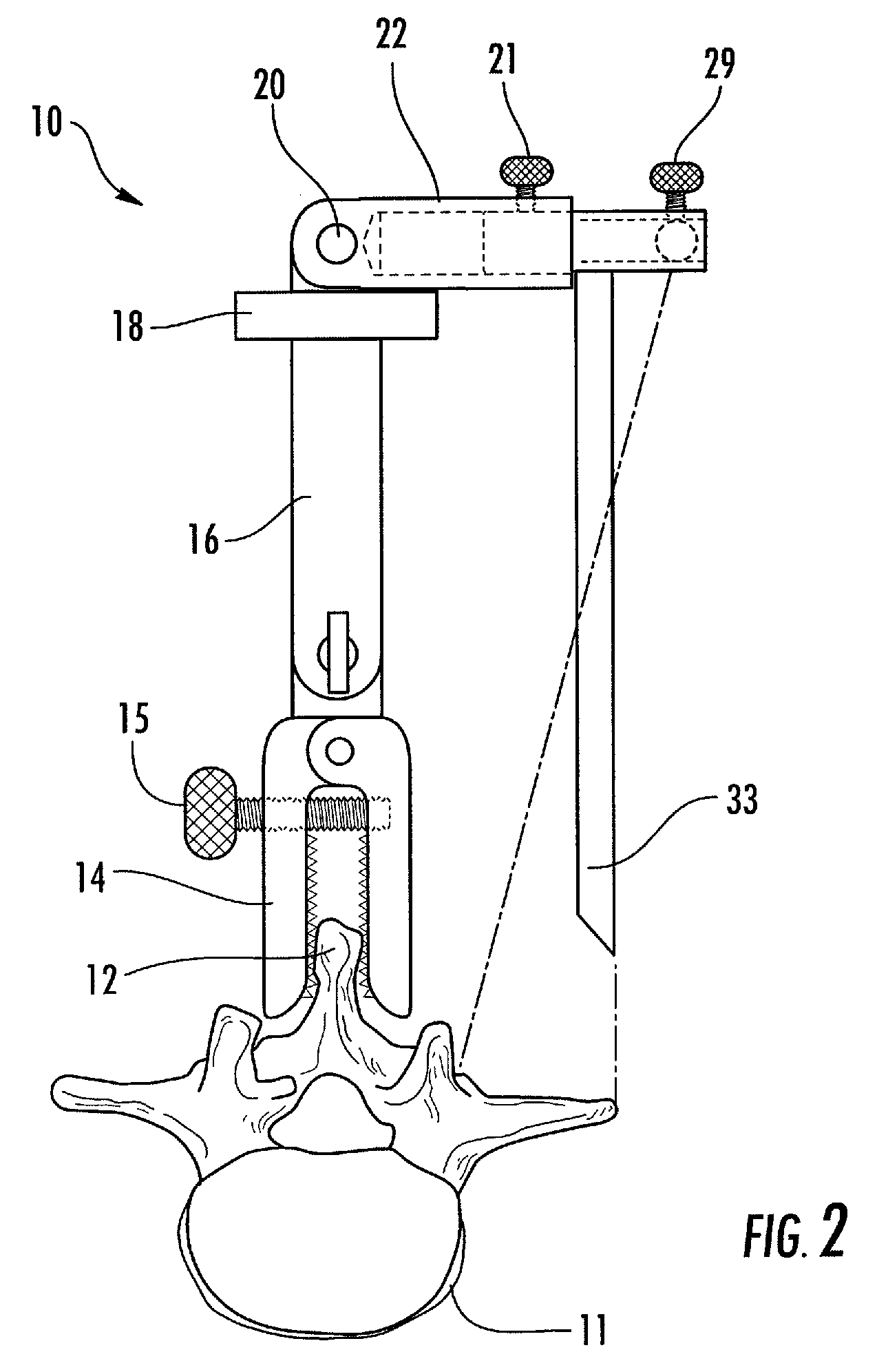
[0014]In an illustrative but non-limiting embodiment the bilaterally positionable drilling and screw placement guide includes a clamp and support assembly adapted for removable engagement with a spinous process of a vertebral body; wherein the support assembly has a distal end incorporating a clamp assembly and a proximal end having a baseplate in rotatable engagement with a bilaterally positionable extension which enables the bilaterally positionable extension to be rotated 180° and thereby be positionable perpendicular to the clamp and support assembly on either side of the body, and further includes a guide and support member for alignment of at least one drill bushing, and at least one bushing fixation support for fixedly engaging at least one drill bushing thereby providing an instrument which enables accurate and repeatable drilling and screw placement within a vertebral body within the axial, coronal and sagittal planes. Optionally, the device may include a pointing device in parallel alignment with the clamp and support assembly for assisting in positioning of the drilling and screw placement guide relative to the vertebral body, and at least one protractor device adapted for rotatable and removable engagement upon the guide and support assembly, and via its rotatable mounting, is adapted for measurement of angles residing within the axial, coronal or sagittal planes.
[0015]In an alternative embodiment the support assembly distal end is constructed and arranged for rotatable engagement with the clamp assembly proximal end which permits adjustments to be made for anatomic anomalies in the spinous process.

Problems solved by technology

However, this guide does not allow for adjustment of the drilling path in the lateral plane of the vertebra.
This device is not useful for fixation to a spinous process.
These references fail to teach or suggest attachment to the spinous process, nor are they adapted for repeatable and reliable alignment to a plurality of angles to enable accurate preparation and placement of fasteners along various spinal aspects.

Method used


Image

  • Spinous process fixated bilateral drilling guide
  • Spinous process fixated bilateral drilling guide
  • Spinous process fixated bilateral drilling guide

Examples


first embodiment

[0053]Now referring to FIG. 1, the bilaterally positionable drilling and screw placement guide, generally referred to as 10, is illustrated fixedly engaged with spinous process 12 which extends from vertebral body 11. Clamp assembly 14 is adapted to fixedly engage the spinous process 12 and be tightened via thumbscrew 15. Tab 19 extends from clamp 14 and couples with support assembly 16. This allows for the surgeon to make minor adjustments to the support mechanism to allow for anatomic anomalies in the spinous process 12. At the uppermost portion of support assembly 16 a base plate 18 is situated, and protruding therefrom is another tab 20, which is inserted into and in rotatable engagement with bilaterally positionable extension 22. This assemblage permits the bilaterally positionable extension 22 to be rotated 180°, thereby permitting the device to be used on either side of the body, while having the extension 22 resting upon base plate 18 causes the bilaterally positionable exte...

embodiment 100

[0056]Referring to FIG. 8, an alternative embodiment 100 is illustrated. In this embodiment the forward edge of bilaterally positionable extension element 52 is dove-tailed, as is that of rotatable extension / bushing support 53. This allows for slidable engagement of polyaxial bushing support 54 and adjustable drill bushing assembly 56 which, by virtue of their attachment to rotatable extension / bushing support 53, permit reliable and repeatable rotation and traversal within the sagittal, coronal and axial planes. By first aligning pointing device 33, which is affixed to slidable element 50, the axial spacing can be delineated. Following this, one degree of adjustment may be affected by virtue of the rotation of the rotatable extension / bushing support 53, while a second degree of adjustment is affected by virtue of rotation and / or traversal of the adjustable drill bushing assembly 56. It is contemplated that plural polyaxial bushing supports 54 and adjustable drill bushing assemblies ...


PUM


Abstract

The application describes a bilateral drilling and screw placement guide adapted for fixation to the spinous process of a vertebral body. The positioning and surgical guiding instrument is adapted for use during a spinal surgical procedure in conjunction with a drilling tool, fastening device, e.g. a pedicle screw, K-wire or the like. The guide includes an engagement device for attachment to a region of the spinous process, to which an adjustably attached support member is affixed. This allows for immobilizing the guide upon the spinous process anatomical landmark, in a specific orientation with respect thereto. The guide includes a bilaterally adjustable drill guide assembly for precise anatomical positioning of the drill and screw placement guides bilaterally about the sagittal, axial and coronal planes so as to enable the defining of a plurality of drilling axes extending toward the vertebral body. The device further provides for adjustment to account for anatomical variations in width along the axial plane, and includes pointing and angular positioning functionality to insure repeatable and reliable pilot hole and screw placement along a plurality of angles.

Description

REFERENCE TO RELATED APPLICATIONS[0001]The present application claims the benefit of priority of U.S. provisional application Ser. No. 61 / 083,014, filed Jul. 23, 2008, the contents of which are incorporated herein by reference.FIELD OF THE INVENTION[0002]This invention relates to drilling guides for safely and accurately establishing drilling and screw placement positions within the spinal anatomy; particularly to a guide which utilizes the spinous process as an anatomical landmark; and most particularly to a bilateral drilling guide which is adapted for fixation to the spinous process, and is constructed to provide repeatable and reliable guidance for placement of drills or screws along plural spinal trajectories.BACKGROUND OF THE INVENTION[0003]The drilling of holes in bones in order to accommodate fastening devices used to anchor implants within a patient's body has become fairly commonplace. In the field of spinal surgery, for example, the use of pedicle screws to anchor interna...

Claims


Application Information

Patent Timeline
Patent Type & Authority Applications(United States)
IPC IPC(8): A61B17/58
CPCA61B17/1757
Inventor THEOFILOS, CHARLES S.
Owner ALPHA GUIDE HLDG LLC
Learn More