
Method and device for receiving and reproducing content

Inactive Publication Date: 2010-01-28
NEC CORP
View PDF11 Cites 19 Cited by
  • Summary
  • Abstract
  • Description
  • Claims
  • Application Information

AI Technical Summary

Benefits of technology

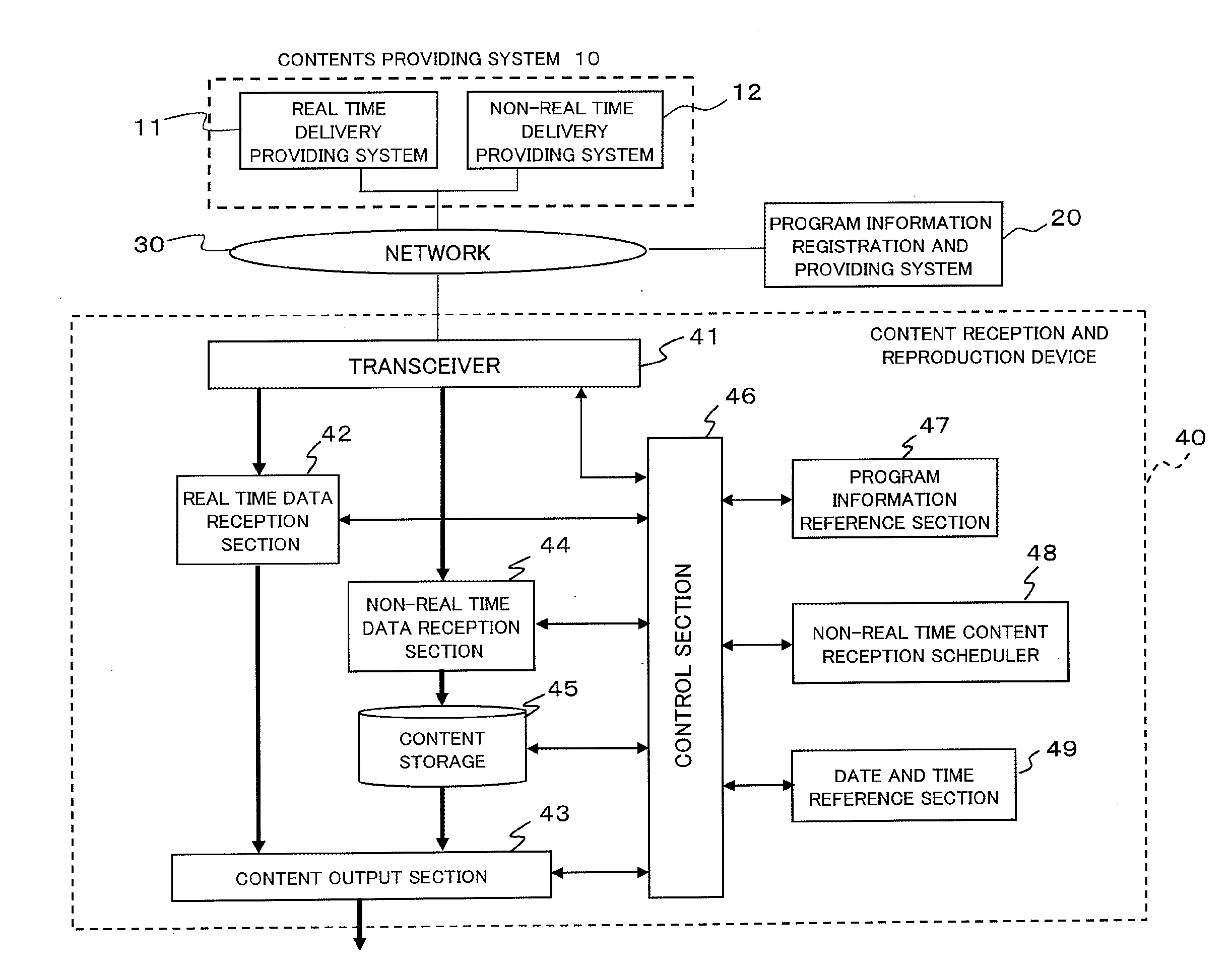
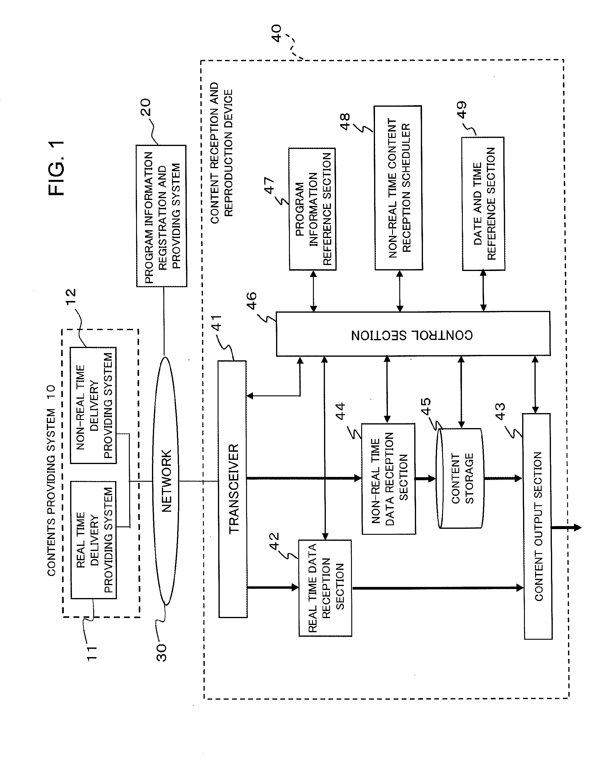
[0027]An object of the present invention is to provide a method and device for receiving and reproducing a content, which allows a content having a reproduction rate higher than a transfer rate or transmission rate, which are restricted depending on a transmission line, to be received and reproduced at the reproduction start time of the content, and also which, even in a case of changing a currently reproduced content to another content having a reproduction rate higher than a transfer rate or transmission rate, allows the new content to be reproduced at its original reproduction rate.
[0030]According to the present invention, it is possible to receive a content having a reproduction rate higher than a transfer rate or transmission rate, which are restricted depending on a transmission line, and to reproduce the content at its reproduction start time. In addition, in a case of changing a currently reproduced content to another content having a reproduction rate higher than a transfer rate or transmission rate, this allows the new content to be reproduced at its original reproduction rate.

Problems solved by technology

Not only in this example, the fact that the bandwidth per channel is fixed imposes a limit on the bit rate at which transmission can be performed using the bandwidth in question.
Accordingly, it is impossible to achieve infinite information transmission rate (bit rate).
First, in a case of displaying images upon receipt of a streaming delivery as in Japanese Patent Application Unexamined Publication No. 2005-210347 and in a case of receiving a digital television broadcast as in Japanese Patent Application Unexamined Publication No. 2007-104588, since a frequency band to be used for communication or broadcasting is predetermined, it is impossible to deliver a content having a reproduction rate greater than the predetermined bandwidth.
For example, in a case where an ADSL transmission line capable of communication at a maximum bit rate of 8 Mbps is used, it is impossible to reproduce a picture signal having a reproduction rate of 20 Mbps by real time delivery because 20-Mbps transfer cannot be made by streaming.
Therefore, it is impossible to transmit / receive a broadcast of a picture signal having a reproduction rate of 30 Mbps.
That is, in this case, it is impossible to receive real time delivery of a picture signal having a reproduction rate of 30 Mbps.
Accordingly, when a program that the audience wants to view has not been downloaded, the downloading of the program is started then, with the result that the program cannot be reproduced immediately, or that the reproduction quality of the content is degraded.
That is, the program content cannot be reproduced at the program start time preset by a contents provider.
Accordingly, for example, when channels are changed, a content may not be able to be reproduced according to a programming schedule, depending on the status of downloading.
Therefore, a live program cannot be delivered or broadcast.
As described above, according to the aforementioned technologies, it is impossible to reproduce a program content having a reproduction rate higher than the transmission rate at the program start time.
In addition, a similar problem may arise with a program content having a reproduction rate higher than the transfer rate that can be used to transfer the program content.
This is because, since the transfer rate is always not higher than the transmission rate, the transfer rate is not higher than the reproduction rate, and therefore, it is impossible to transmit information in the amount required for reproduction.
Therefore, if a content to be downloaded for the following day has a very large amount of information, the problem may arise that the amount to be downloaded is so large that the downloading cannot be completed before the program start time.

Method used


Image

  • Method and device for receiving and reproducing content
  • Method and device for receiving and reproducing content
  • Method and device for receiving and reproducing content

Examples


first example

2. FIRST EXAMPLE

2.1) Configuration

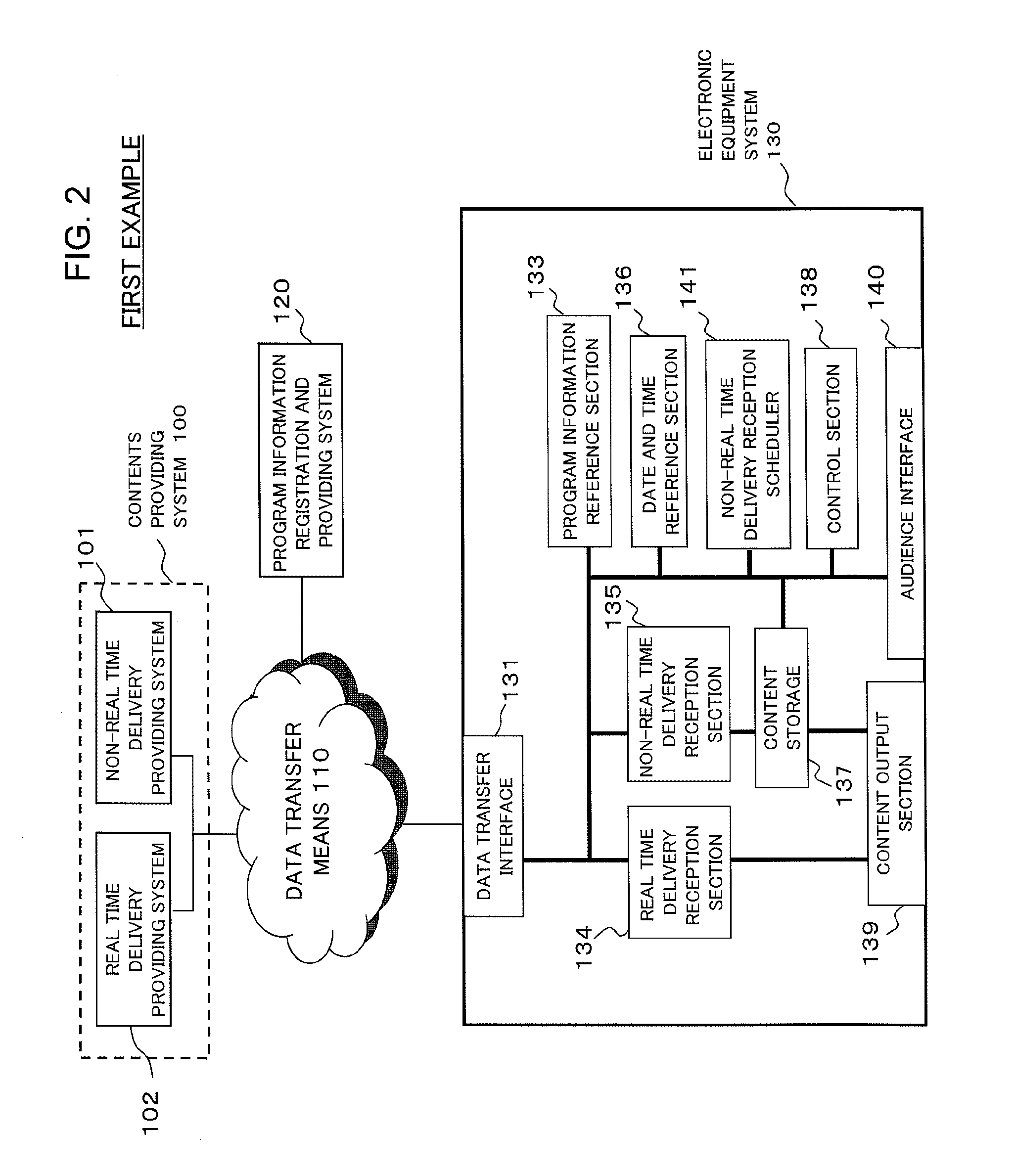
[0064]FIG. 2 is a block diagram showing a schematic configuration of an electronic equipment system in a content delivery system according to a first example of the present invention. Here, it is assumed that an electronic equipment system 130 can connect to a contents providing system 100 and a program information registration and providing system 120 through data transfer means 110. The program information registration and providing system 120 accepts, for each program content, the registration of a program identifier, a program start date and time, and a program delivery method from a content supplier and keeps the information. The program identifier is a combination of symbols, such as alphanumeric characters, that is assigned to a program content so that the program content can be uniquely specified. A character sequence composed of a combination of a channel and a program start date and time can also be treated as a program identifier if a con...

second example

9. SECOND EXAMPLE

[0162]As a second example of the present invention, a system will be described that uses, as real time delivery methods, both of a method using streaming delivery and a method making delivery by radio-wave broadcasting or through cable by modulating a high-frequency electric signal such as CATV.

[0163]FIG. 10 is a block diagram showing a schematic configuration of an electronic equipment system in a content delivery system according to a second example of the present invention. Note that blocks having functions similar to those shown in FIG. 2 are denoted by the same reference numerals in FIG. 2, and a description thereof will be omitted where appropriate.

[0164]In the present example, two types of real time delivery providing system are provided: a broadcasting station 900 and a streaming sever 902. The broadcasting station 900 has a function of transmitting a broadcast signal or CATV signal by modulating a high-frequency carrier based on a picture signal, regardless...

third example

10. THIRD EXAMPLE

[0187]According to a third example of the present invention, a mechanism is additionally provided that prevents an audience from viewing a downloaded program content before the program start time. Such a new challenge is addressed because it is a general rule in television broadcasting that a audience cannot view a content before the program start time of the content.

[0188]In the first example shown in FIG. 2, a clock (the date and time reference section 136) to refer to is predetermined, and a user refers to the clock, thereby referencing the current time (see, for example, the description at Step 405 in FIG. 5 and the like) When the current time coincides with the program start time of a program content, the reproduction of the program content is started. Assuming that no malicious user exists, a program cannot be viewed unless its program start time has come as in the case of television broadcasting. However, a malicious user might try to view a downloaded file b...


PUM


Abstract

A content reception and reproduction device which receives and reproduces a content having at least one reproduction start time predetermined, includes: a non-real time receiver for receiving a content in non-real time; a program information reference section for referring to program information which includes a reproduction start time of at least one content and a delivery method of said at least one content; a scheduler for scheduling reception of a content whose delivery method is non-real time delivery by the non-real time receiver based on a current time and a reproduction start time of the content; a content storage section for storing at least one content received by the non-real time receiver; and a controller for starting reproduction of a content stored in the content storage section at the reproduction start time of the content.

Description

[0001]This application is based upon and claims the benefit of priority from Japanese Patent Application No. 2008-190480, filed on Jul. 24, 2008, the disclosure of which is incorporated herein in its entirety by reference.BACKGROUND OF THE INVENTION[0002]I. Field of the Invention[0003]The present invention relates to a method and device for receiving and reproducing a content comprised of picture or images, sound, and the like as well as an electronic equipment system for receiving and reproducing the content.[0004]2. Description of the Related ArtI. Description of Terms[0005]First of all, a brief mention is made of several terms used in a description of the technologies related to the present invention.[0006]Real time delivery is a delivery method in which a receiving side sequentially reproduces a content (e.g., images and sound) upon receipt thereof without waiting for the transfer, from the sending side to the receiving side, of the whole content from beginning to end to be comp...

Claims


Application Information

Patent Timeline
IPC IPC(8): H04N5/91H04N5/765H04N5/93H04N7/173H04N21/433H04N21/458
CPCH04H20/40H04L67/289H04N7/17327H04N21/2393H04N21/26216H04N21/26241H04N21/4325H04N21/4331H04N21/458H04N21/47214H04L65/4084H04L67/104H04L67/06H04L67/325H04H40/09H04L65/612H04L67/62
Inventor SHIRAGAKI, TATSUYAMIYAO, YASUHIRO
Owner NEC CORP
Learn More