
Dynamic gamut control

a gamut control and dynamic technology, applied in the field of dynamic gamut control, to achieve the effect of reducing power consumption

Inactive Publication Date: 2010-01-28
KONINKLIJKE PHILIPS ELECTRONICS NV
View PDF11 Cites 21 Cited by
  • Summary
  • Abstract
  • Description
  • Claims
  • Application Information

AI Technical Summary

Benefits of technology

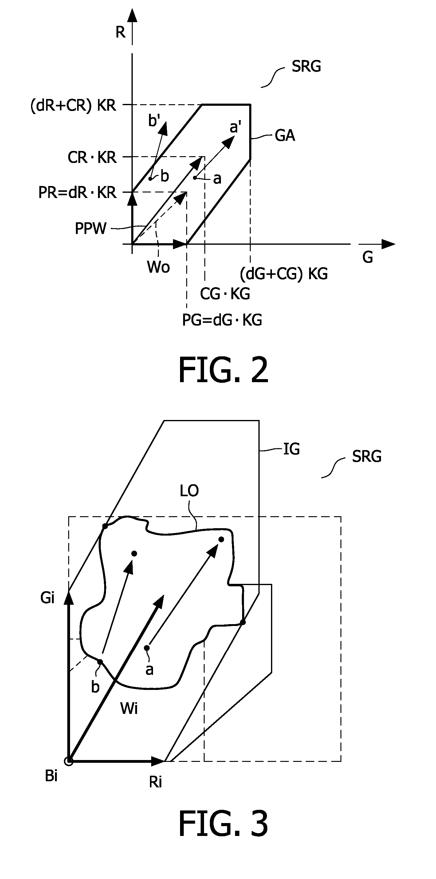
[0012]This step-by-step decrease of the gamut minimizes the intensity of the color primaries and thus the power to be supplied to the light sources, while on the other hand care is taken to not change the gamut such that any colors of the image are outside the gamut. The actual intensities of the color primaries and thus the resulting gamut are dynamically controlled to fit all the colors of the actual image with minimal intensity of the primaries.
[0018]In an embodiment, for each color of the set of colors, the minimal intensity value of the adjusted color primary is found by substituting coordinates of the projection of the selected color of the set of colors in an equation defining a boundary line of the boundary of the adjusted two-dimensional color gamut. Consequently, the intensity value of the adjusted color primary for which the color lies on a boundary of the two-dimensional color gamut is easily found by using linear equations defining lines. It is not required to perform difficult matrix operations in an N-dimensional space.

Problems solved by technology

The color may lie exactly on the boundary, but may have a small offset with respect to the boundary due to quantization errors.

Method used


Image

  • Dynamic gamut control
  • Dynamic gamut control
  • Dynamic gamut control

Examples


Embodiment Construction

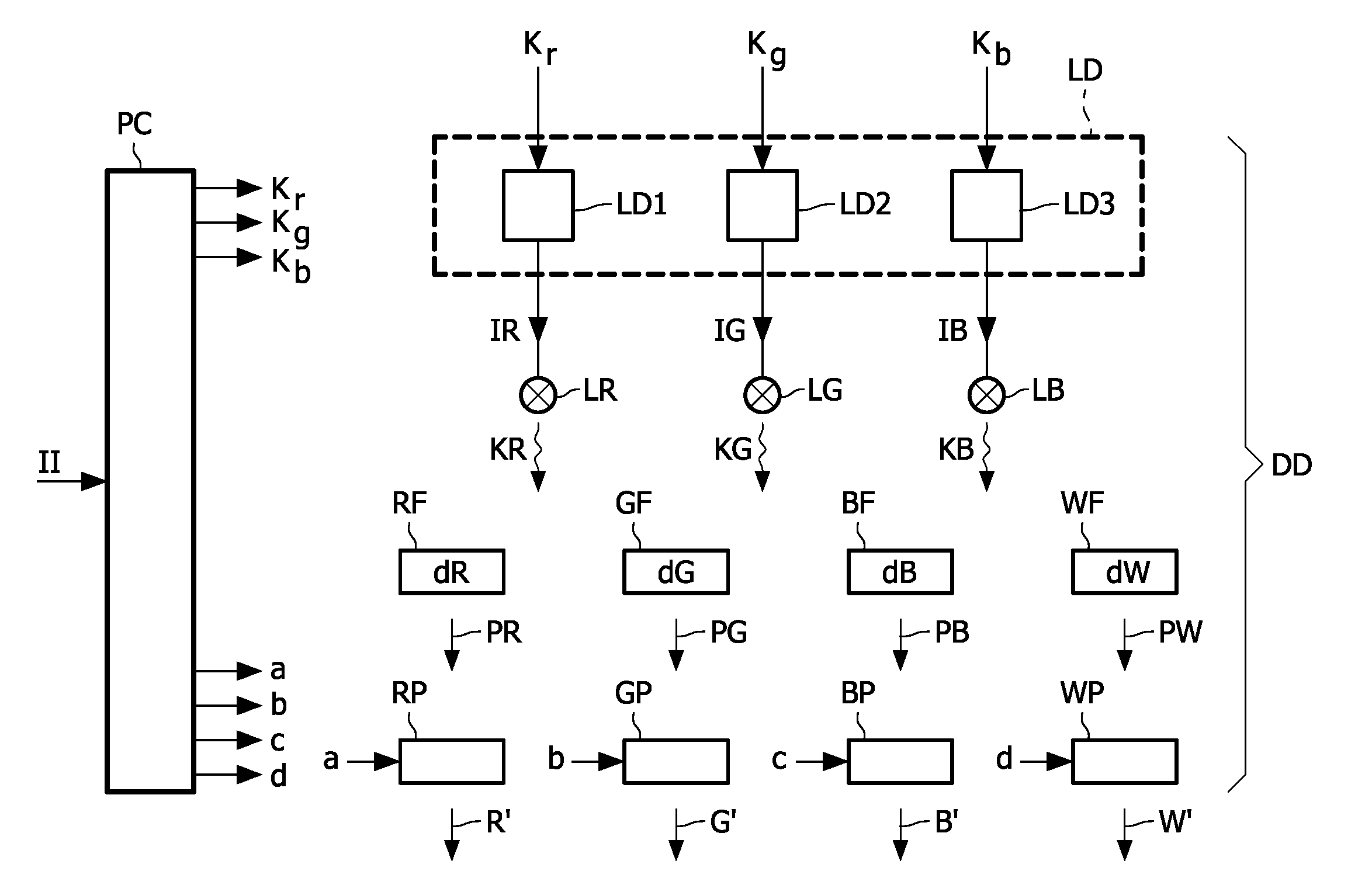
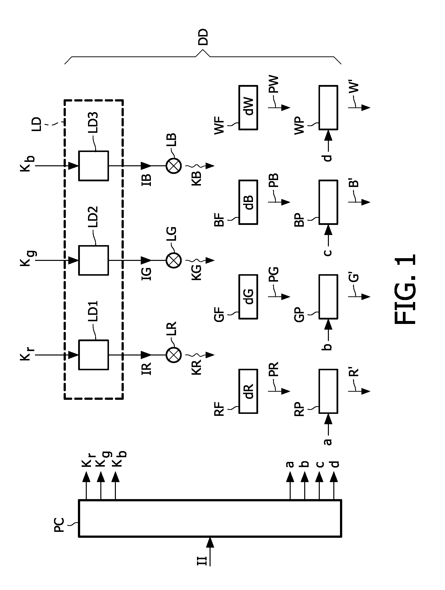
[0036]FIG. 1 shows a schematic block diagram of a processor and a display device. The display device DD uses N color primaries, which are generated by P light sources via N color filters, which have a particular transmission. In FIG. 1 an example is shown with N=4 primaries PR, PG, PB, PW, three light sources LR, LG, LB, and four color filters RF, GF, BF, WF. In the now following the invention is elucidated with respect to this example because an explanation for larger values of N and P would become needless complex. The skilled person will easily be able to understand from the explanation with respect to this example that the invention is applicable to a general case for N primaries, P light sources, and N color filters.

[0037]The color primaries PR, PG, PB, PW illuminate the associated sub-pixels RP, GP, BP, WP, respectively of a pixel of the display device DD. The optical state of the sub-pixels RP, GP, BP, WP is controlled by the control signals a, b, c, d, respectively, in accor...


PUM


Abstract

A method of dynamic gamut control comprises the step of controlling (LD) intensities of at least a subset (PR, PG, PB) of a set of color primaries (PR, PG, PB, PW) associated with corresponding sub-pixels (RP, GP, BP, WP) of a display device. The method further comprises the step of searching (PC) for a minimal intensity value (Ra; Ga; Ba) of one of the color primaries of the subset (PR; PG; PB) being adjusted, to obtain together with the other color primaries (WP) of the set of color primaries (PR, PG, PB, PW) an adjusted color gamut (GG1; GR1; GB1; GG2; GR2) still containing all the colors of the set of colors (S) by: for each color of the set of colors (S), determining (PC) the minimal intensity value (Ra; Ga; Ba) of the color primary being adjusted to obtain the adjusted color gamut (GG1; GR1; GB1; GG2; GR2) wherein the selected color of the set of colors (S) lies substantially on a boundary of the adjusted color gamut (GG1; GR1; GB1; GG2; GR2), and selecting (PC) a maximum value of the determined minimal intensity values (Ra; Ga; Ba) of the color primary being adjusted.

Description

FIELD OF THE INVENTION[0001]The invention relates to a method of dynamic gamut control, a dynamic gamut control unit, a display apparatus comprising the dynamic gamut control unit, a handhold apparatus with a display and comprising the dynamic gamut control unit, and a computer program product.BACKGROUND OF THE INVENTION[0002]Many display apparatuses display images on a display device by using a light unit, which comprises at least one light source for illuminating the pixels of a pixilated display device. Usually, the pixilated display is a matrix display. Usually, in a stable operation state, the light source provides a non-varying light spectrum and the input image is reproduced by modulating the optical state of the pixels. Up till now, predominantly fluorescent lamps are used as the light source. However, LED's, which supply almost monochromatic spectra, are also considered. A known transmissive LCD display comprises pixels made of LC material of which an optical transmission i...

Claims


Application Information

Patent Timeline
Patent Type & Authority Applications(United States)
IPC IPC(8): G09G5/10
CPCG09G3/2003G09G3/3413G09G2300/0452G09G2340/06G09G2320/064G09G2320/0646G09G2320/0666G09G2320/0633
Inventor BELIK, OLEGZNAMENSKIY, DMITRY NIKOLAEVICH
Owner KONINKLIJKE PHILIPS ELECTRONICS NV
Learn More