Anatomical visualization and measurement system

Active Publication Date: 2010-01-21
ASTUTE IMAGING LLC
View PDF0 Cites 40 Cited by
  • Summary
  • Abstract
  • Description
  • Claims
  • Application Information

AI Technical Summary

Benefits of technology

[0020]Accordingly, one object of the present invention is to provide an improved anatomical visualization and measurement system for visualizing and measuring anatomical structures.
[0021]Another object of the present invention is to provide an improved anatomical visualization and measurement system wherein a scanned 2D slice image can be appropriately combined with an image generated from a 3D database so as to create a single composite image.
[0022]Another object of the present invention is to provide an improved anatomical visualization and measurement system wherein a marker can be placed onto a 2D slice image displayed on a screen, and this marker will be automatically incorporated, as appropriate, into a 3D computer model maintained by the system, as well as into any other 2D slice image data maintained by the system.

Problems solved by technology

Furthermore, in many cases, the anatomical structures of interest to the physician may be quite small and / or difficult to identify with the naked eye.
While the 2D slice images generated by the aforementioned scanning devices, and / or the 3D database images generated by the aforementioned associated computer hardware and software, are generally of great benefit to physicians, certain significant limitations still exist.
Unfortunately, physicians can sometimes have difficulty correlating what they see on one image with what they see on another image.
In these situations it can be relatively difficult and / or time-consuming for the physician to accurately measure and record all of the anatomical dimensions needed for proper sizing of the prosthetic device to the patient.
Unfortunately, it can be difficult and / or impossible to make accurate anatomical measurements with existing visualization systems.
Unfortunately, it can be difficult and / or impossible to accurately generate such a view using existing visualization systems.
Unfortunately, it can be difficult and / or impossible to accurately make such a calculation using existing visualization systems.
Unfortunately, current visualization systems do not provide simple and effective features for providing such modeling.

Method used


Image

  • Anatomical visualization and measurement system
  • Anatomical visualization and measurement system
  • Anatomical visualization and measurement system

Examples


Embodiment Construction

1. Basic System

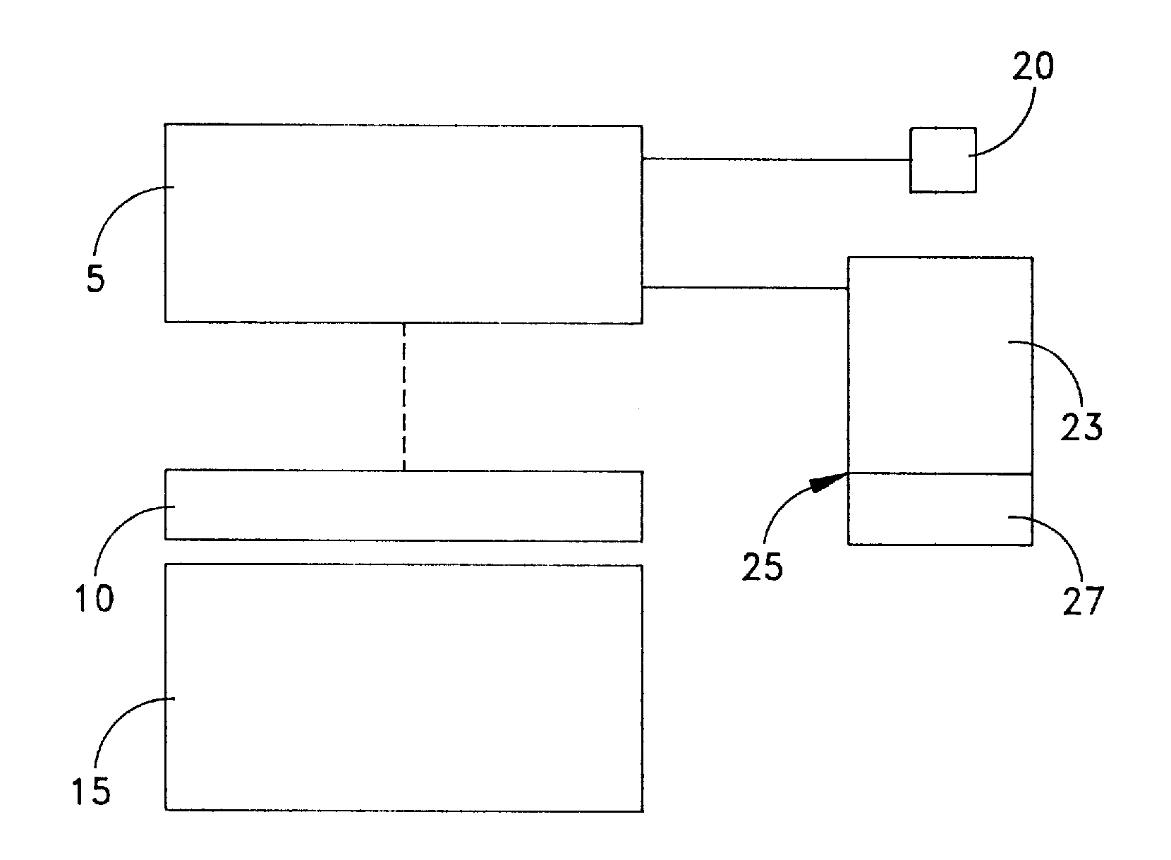
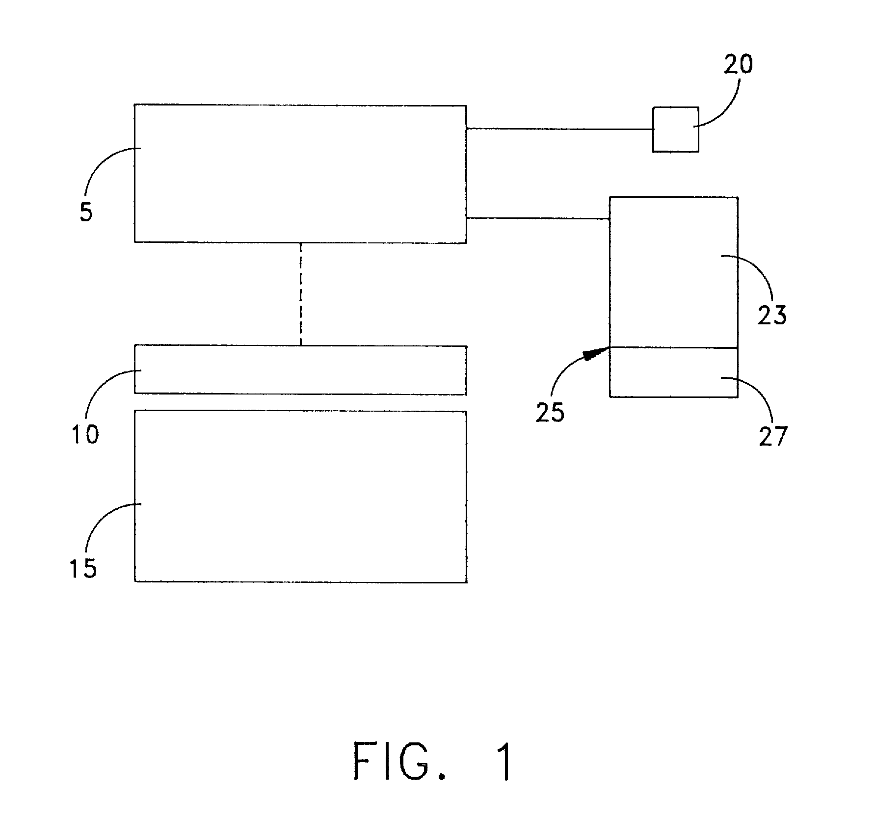
[0197]Looking first at FIG. 1, a scanning device 5 is shown as it scans the interior anatomical structure of a patient 10, as that patient 10 lies on a scanning platform 15.

[0198]Scanning device 5 is of the sort adapted to generate scanning data corresponding to a series of 2D images, where each 2D image corresponds to a specific viewing plane or “slice” taken through the patient's body. Furthermore, scanning device 5 is adapted so that the angle and spacing between adjacent image planes or slices can be very well defined, e.g., each image plane or slice may be set parallel to every other image plane or slice, and adjacent image planes or slices may be spaced a pre-determined distance apart. By way of example, the parallel image planes might be set 1 mm apart.

[0199]The scanning data obtained by scanning device 5 can be displayed as a 2D slice image on a display 20, and / or it can be stored in its 2D slice image data form in a first section 23 of a data storage device o...


PUM


Abstract

A method for deploying a device in a tortuous vessel, comprising:creating a virtual representation of the tortuous vessel;placing a virtual generalized-cylinder within the virtual representation of the tortuous vessel, wherein the virtual generalized-cylinder is placed within the virtual representation of the tortuous vessel by (i) calculating the centerline of the virtual representation of the tortuous vessel, and (ii) generating the virtual generalized-cylinder by defining an extent along the centerline of the virtual representation of the tortuous vessel and constructing the virtual generalized-cylinder about the centerline;measuring length along the perimeter of the virtual generalized-cylinder at a pre-determined number of longitudes, wherein the longitudes extend parallel to the centerline, and further wherein measuring length along the perimeter of the virtual device at a pre-determined number of longitudes comprises marching down the centerline of the virtual generalized-cylinder, incrementally adding to an array of longitudinal length counters as progressing along the centerline;determining the maximum measured length;selecting a device based upon the maximum measured length; anddeploying the device in the tortuous vessel.

Description

REFERENCE TO PENDING PRIOR PATENT APPLICATIONS[0001]This patent application:[0002](i) is a continuation-in-part of pending prior U.S. patent application Ser. No. 11 / 732,291, filed Apr. 3, 2007 by David Chen et al. for ANATOMICAL VISUALIZATION AND MEASUREMENT SYSTEM (Attorney's Docket No. MMS-36); and[0003](ii) claims benefit of U.S. Provisional Patent Application Ser. No. 61 / 063,992, filed Feb. 7, 2008 by Hui Zou et al. for PREVIEW 2.9 INNER AND OUTER CURVE CALCULATION (Attorney's Docket No. MMS-39 PROV).[0004]The two above-identified patent applications are hereby incorporated herein by reference.FIELD OF THE INVENTION[0005]This invention relates to medical apparatus in general, and more particularly to anatomical visualization and measurement systems.BACKGROUND OF THE INVENTION[0006]Many medical procedures must be carried out at an interior anatomical site which is normally hidden from the view of the physician. In these situations, the physician typically uses some sort of scanni...

Claims


Application Information

Patent Timeline
IPC IPC(8): A61B1/00G06K9/00
CPCG06T7/0012G06T7/602G06T2207/30101G06T2207/10072G06T2207/20044G06T17/10G06T7/62
Inventor ZOU, HUICHEN, DAVID
Owner ASTUTE IMAGING LLC
Why Eureka
Try Eureka