
Golf club head having trip step feature

a golf club and feature technology, applied in the field of sport equipment, can solve the problems of significant adverse effects observed in these large fb dimension golf clubs, dramatic reduction of club head speed, and golf club designers pay little attention to the aerodynamics of these large golf clubs, so as to reduce the aerodynamic drag force, reduce the aerodynamic drag, and increase the skin friction

Inactive Publication Date: 2010-01-21
TAYLOR MADE GOLF
View PDF50 Cites 156 Cited by
  • Summary
  • Abstract
  • Description
  • Claims
  • Application Information

AI Technical Summary

Benefits of technology

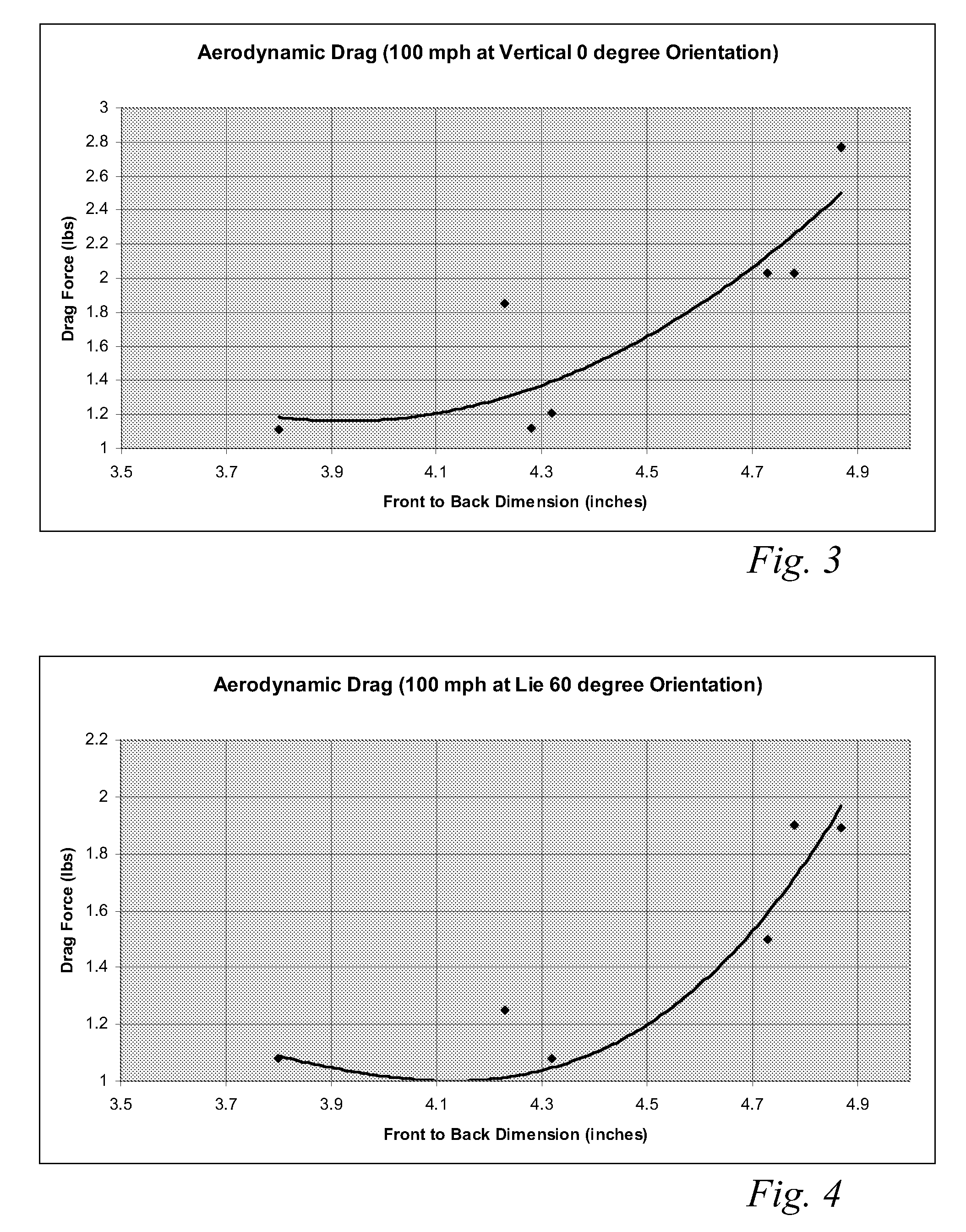
[0019]The trip step enables a significant reduction in the aerodynamic drag force exerted on the golf club head by forcing the air passing over the club head from laminar flow to turbulent flow just before the natural separation point of the airstream from the crown. This selectively engineered transition from laminar to turbulent flow over the crown section slightly increases the skin friction but results in less aerodynamic drag than if the air were to detach from the crown section at the natural separation point.

Problems solved by technology

Still, golf club designers pay little attention to the aerodynamics of these large golf clubs; often instead focusing solely on increasing the club head's resistance to twisting during off-center shots.
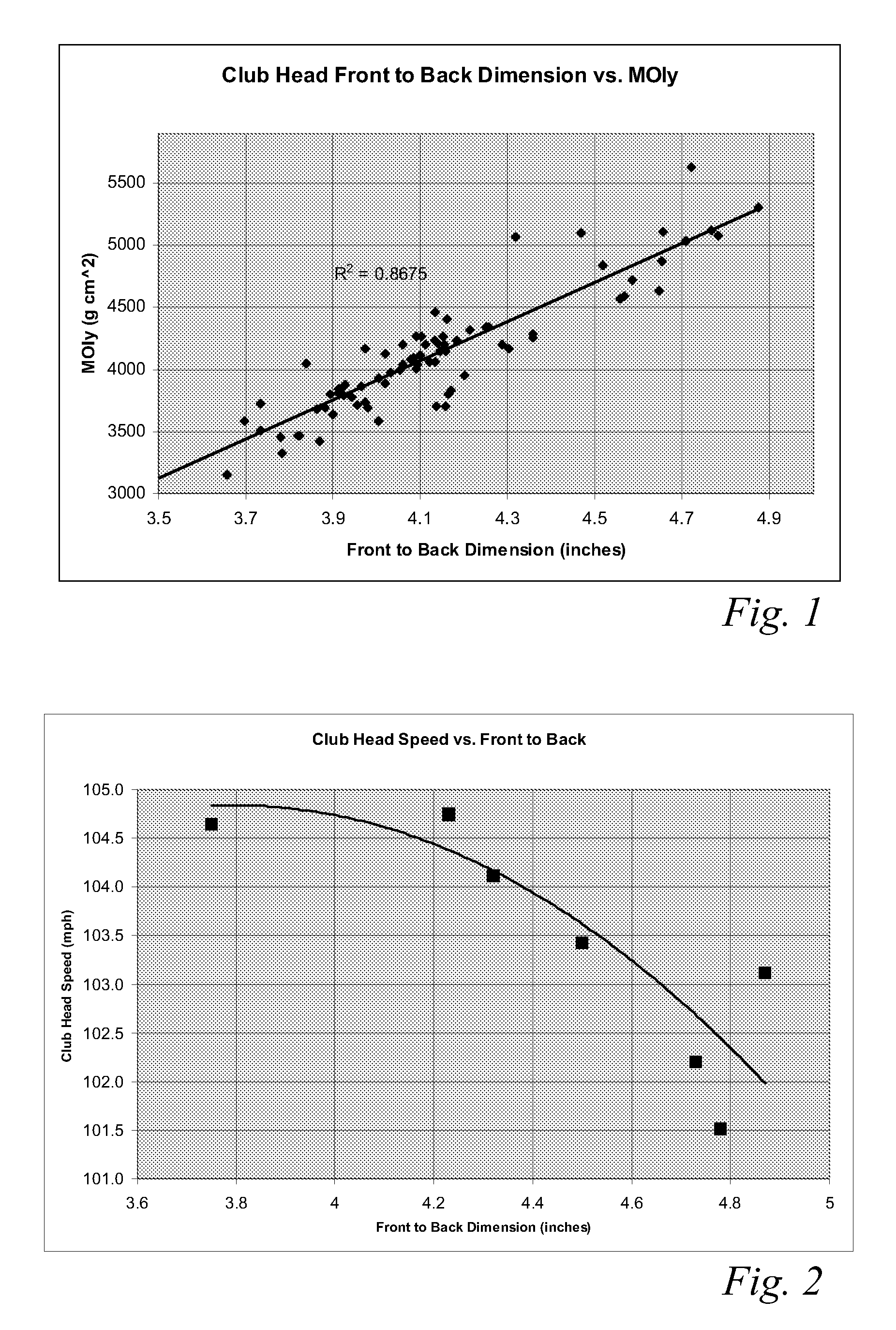
While increasing the FB dimension to achieve higher MOIy values is logical, significant adverse effects have been observed in these large FB dimension clubs.
One significant adverse effect is a dramatic reduction in club head speed, which appears to have gone unnoticed by many in the industry.
This significant decrease in club head speed is the result of the increase in aerodynamic drag forces associated with large FB dimension golf club heads.
In fact, for a club head speed of approximately 100 mph, each 1 mph reduction in club head speed results in approximately a 1% loss in distance.

Method used


Image

  • Golf club head having trip step feature
  • Golf club head having trip step feature
  • Golf club head having trip step feature

Examples


Embodiment Construction

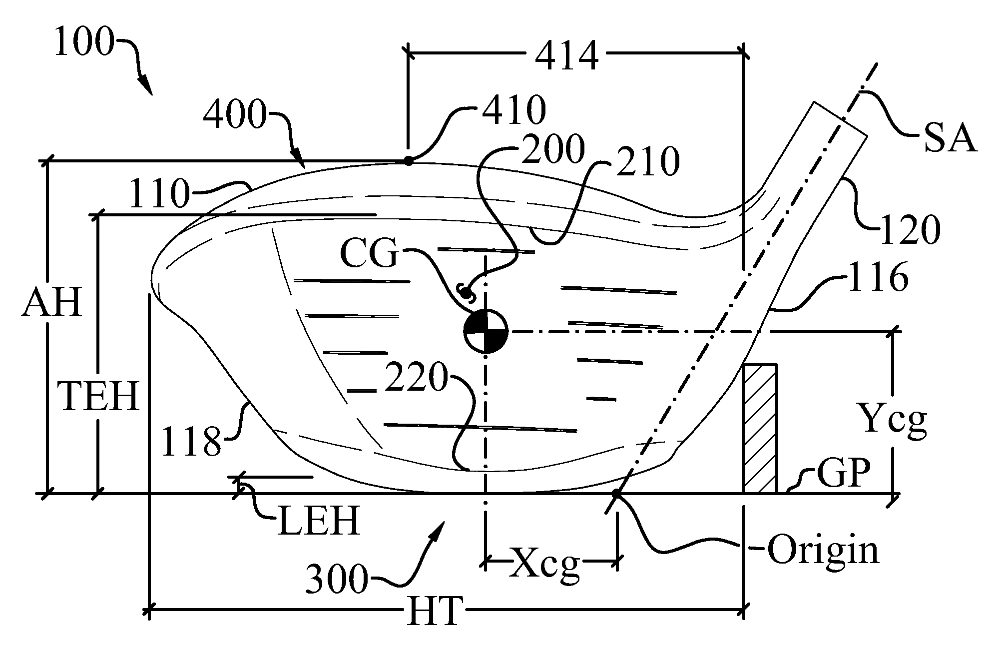
[0058]The claimed aerodynamic golf club head (100) enables a significant advance in the state of the art. The preferred embodiments of the aerodynamic golf club head (100) accomplish this by new and novel arrangements of elements and methods that are configured in unique and novel ways and which demonstrate previously unavailable but preferred and desirable capabilities. The description set forth below in connection with the drawings is intended merely as a description of the presently preferred embodiments of the aerodynamic golf club head (100), and is not intended to represent the only form in which the aerodynamic golf club head (100) may be constructed or utilized. The description sets forth the designs, functions, means, and methods of implementing the aerodynamic golf club head (100) in connection with the illustrated embodiments. It is to be understood, however, that the same or equivalent functions and features may be accomplished by different embodiments that are also inte...


PUM


Abstract

An aerodynamic golf club head incorporating a trip step feature located on the crown section. The benefits associated with the reduction in aerodynamic drag force associated with the trip step may be applied to drivers, fairway woods, and hybrid type golf club heads. The trip step is located between a crown apex and the back of the club head and may be continuous or discontinuous. The trip step enables a significant reduction in the aerodynamic drag force exerted on the golf club head by forcing the air passing over the club head from laminar flow to turbulent flow just before the natural separation point of the airstream from the crown. This selectively engineered transition from laminar to turbulent flow over the crown section slightly increases the skin friction but results in less aerodynamic drag than if the air were to detach from the crown section at the natural separation point.

Description

CROSS-REFERENCE TO RELATED APPLICATIONS[0001]This application claims the benefit of U.S. provisional patent application Ser. No. 61 / 080,892, filed on Jul. 15, 2008, and U.S. provisional patent application Ser. No. 61 / 101,919, filed on Oct. 1, 2008, all of which are incorporated by reference as if completely written herein.STATEMENT REGARDING FEDERALLY SPONSORED RESEARCH OR DEVELOPMENT[0002]This invention was not made as part of a federally sponsored research or development project.TECHNICAL FIELD[0003]The present invention relates to sports equipment; particularly, to an aerodynamic golf club head having a trip step feature.BACKGROUND OF THE INVENTION[0004]Modern high volume golf club heads, namely drivers, are being designed with little, if any, attention paid to the aerodynamics of the golf club head. This stems in large part from the fact that in the past the aerodynamics of golf club heads were studied and it was found that the aerodynamics of the club head had only minimal impa...

Claims


Application Information

Patent Timeline
IPC IPC(8): A63B53/04
CPCA63B53/0466A63B2053/0408A63B2053/0437A63B2053/0412A63B2059/0011A63B2225/01A63B53/0408A63B53/0412A63B53/0437A63B60/006A63B53/04
Inventor BURNETT, MICHAEL SCOTTSCHMIDT, MARC
Owner TAYLOR MADE GOLF
Learn More