
Switching power amplifier and method of controlling the same

a power amplifier and switching technology, applied in the direction of dc amplifiers with modulator-demodulator, amplifiers with semiconductor devices/discharge tubes, amplifiers to reduce noise influence, etc., can solve the problems of low efficiency, large power loss, and the performance of switching power amplifiers may be degraded, so as to remove the non-linearity of switching power amplifiers

Active Publication Date: 2010-01-21
SAMSUNG ELECTRONICS CO LTD
View PDF37 Cites 25 Cited by
  • Summary
  • Abstract
  • Description
  • Claims
  • Application Information

AI Technical Summary

Benefits of technology

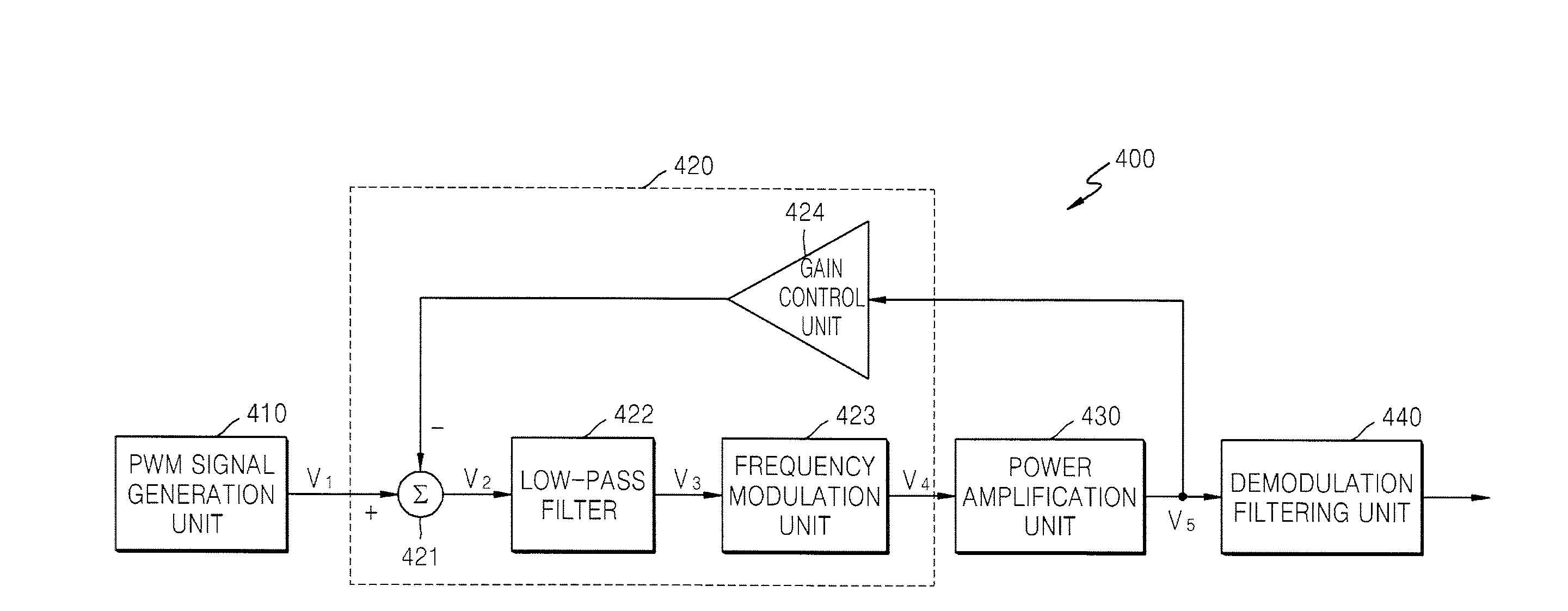
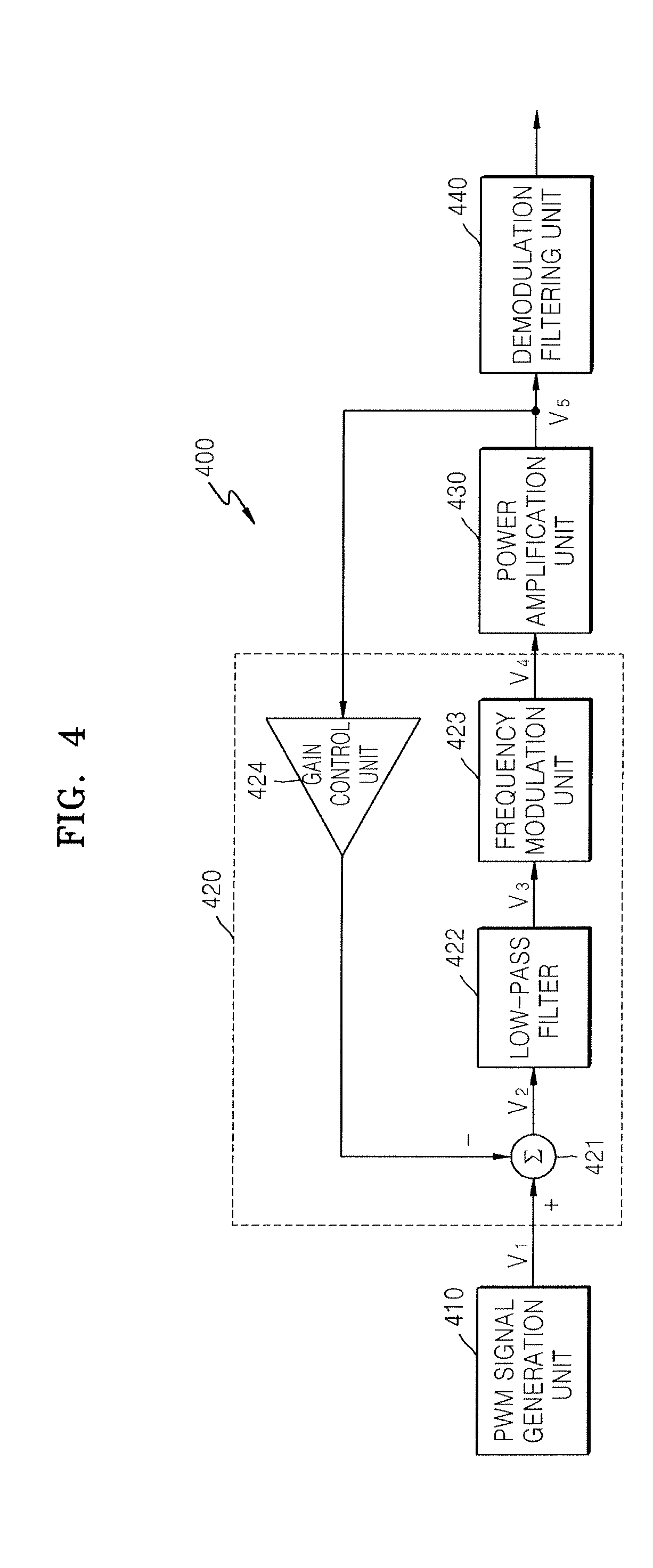
[0006]The present general inventive concept provides a switching power amplifier that changes the frequency of a pulse width modulation (PWM) signal input to a power stage in order to remove non-linearity of the switching power amplifier, and a method of controlling the switching power amplifier.
[0009]According to embodiments of the present general inventive concept, an input PWM signal is modulated to have a switching frequency different from a carrier frequency component originally included in the input PWM signal, thereby improving the frequency characteristics of a power amplification unit and correcting the non-linearity of the power amplification unit.

Problems solved by technology

These linear analog power amplifiers have good linearity but provide low efficiency, thus resulting in large power loss.
However, the performance of switching power amplifiers may be degraded due to the non-linearity of the power switch stage.
The non-linearity of the power switch stage degrades the total harmonic distortion (THD) and generates out of band noise, thereby degrading the signal-to-noise ratio (SNR).
In addition, noise is generated in an output signal due to the non-linearity and ripple of the power unit connected to the power switch stage of the switching power amplifiers.

Method used


Image

  • Switching power amplifier and method of controlling the same
  • Switching power amplifier and method of controlling the same
  • Switching power amplifier and method of controlling the same

Examples


Embodiment Construction

[0026]Reference will now be made in detail to the embodiments of the present general inventive concept, examples of which are illustrated in the accompanying drawings, wherein like reference numerals refer to the like elements throughout. The embodiments are described below in order to explain the present general inventive concept by referring to the figures.

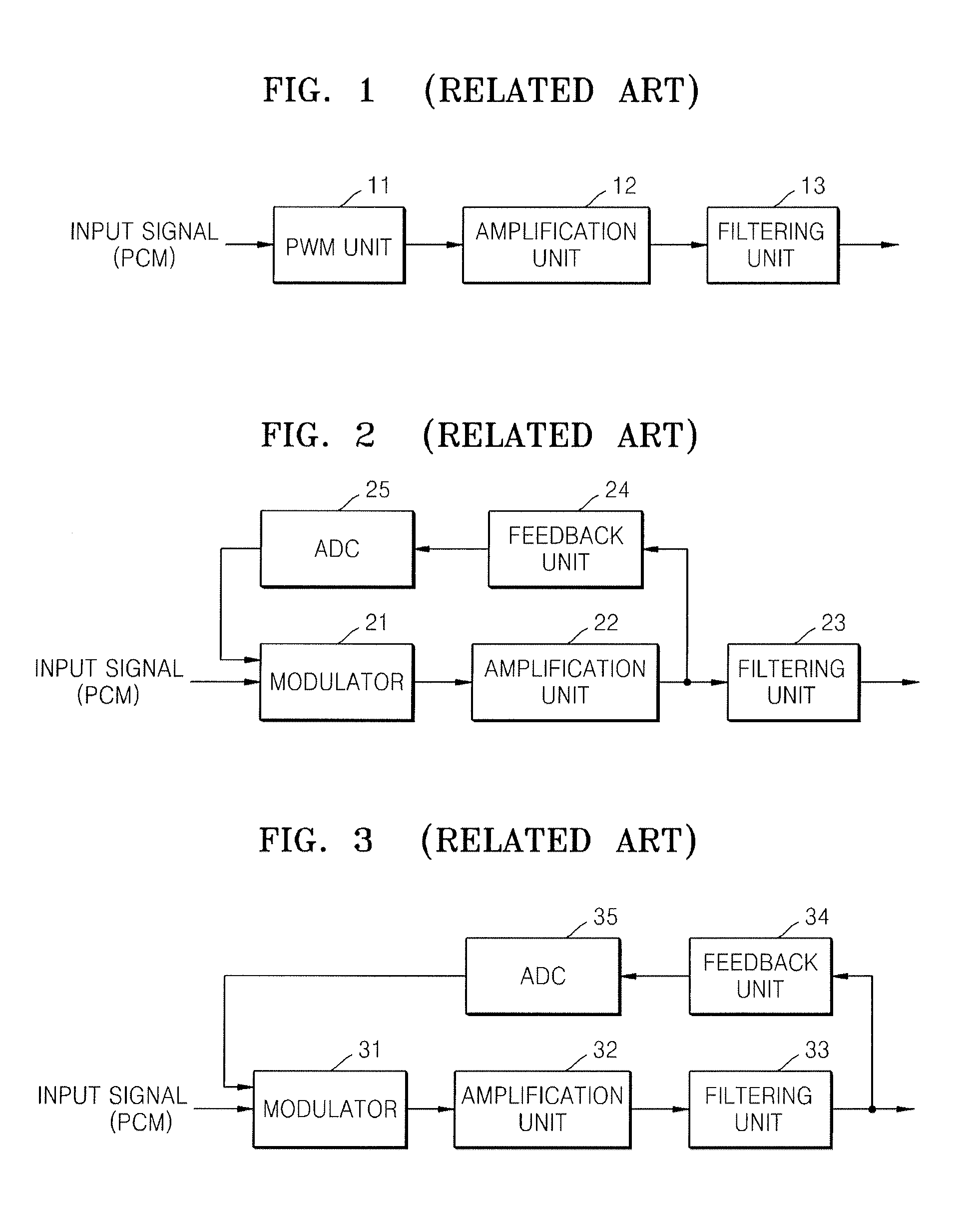
[0027]FIG. 1 is a block diagram of an example of a switching power amplifier in the related art. A switching power amplifier uses a pulse width modulation (PWM) method in which amplification is performed by switching. Referring to FIG. 1, a PWM unit 11 modulates an input signal PCM into a PWM signal, an amplification unit 12 amplifies the input signal according to a switching operation depending on the PWM signal, and a filtering unit 13, which may be a low-pass filter, extracts an audio waveform from the amplified input signal. As described above, the conventional switching power amplifier of FIG. 1 generates distortion of an o...


PUM


Abstract

A switching power amplifier having a pulse width modulation (PWM) signal generation unit that converts an input audio signal into a PWM signal with a predetermined carrier frequency, a correction unit that corrects the difference between an audio signal included in the PWM signal and a negative feedback output audio signal to generate a corrected PWM signal, a low pass filter that removes a high-frequency component from the corrected PWM signal, a frequency modulation unit that modulates the corrected PWM signal so that the corrected PWM signal has a switching frequency different from the carrier frequency of the input PWM signal to generate a modulated PWM signal, and a power amplification unit that amplifies a power of the modulated PWM signal.

Description

CROSS-REFERENCE TO RELATED APPLICATIONS[0001]This application priority under 35 U.S.C. § 119(a) Korean Patent Application No. 10-2008-0069311, filed on Jul. 16, 2008, and Korean Patent Application No. 10-2009-0027754, filed on Mar. 31, 2009, in the Korean Intellectual Property Office, the disclosures of which are incorporated herein in their entirety by reference.BACKGROUND[0002]1. Field of the Invention[0003]The present general inventive concept relates to a switching power amplifier, and more particularly, to a switching power amplifier that removes non-linearity of a power amplification unit by converting an input audio signal into a pulse width modulation (PWM) signal, removing a carrier frequency from a the PWM signal, and modulating the PWM signal so that the PWM signal has a new frequency for operation of a power stage.[0004]2. Description of the Related Art[0005]Class-A power amplifiers, class-B power amplifiers, and class-AB power amplifiers are generally used as linear ana...

Claims


Application Information

Patent Timeline
Patent Type & Authority Applications(United States)
IPC IPC(8): H03F3/38
CPCH03F3/2173H03F1/26H03F3/217H03F2200/348H03F2200/351H03F3/2175H03K7/08
Inventor PARK, HAE-KWANG
Owner SAMSUNG ELECTRONICS CO LTD
Learn More