
Tunable Radio-Frequency Coil

Active Publication Date: 2010-01-21
THE BOARD OF TRUSTEES OF THE UNIV OF ILLINOIS
View PDF5 Cites 7 Cited by
  • Summary
  • Abstract
  • Description
  • Claims
  • Application Information

AI Technical Summary

Benefits of technology

[0013]Yet another embodiment provides a method for tuning an RF coil used in a magnetic resonance apparatus. The RF coil includes at least one closed-curve conductor having an axis. The axis and the closed-curve conductor define a tubular surface. Leg conductors are disposed, in a spaced-apart relation, along the tubular surface. The legs are parallel to the axis and are electrically connected at their first ends to the closed-curve conductor. The RF coil is tuned by positioning the tuning band (including a capacitor closed about the conductive legs) so as to place each and every conductive leg in proximity to and extending along the surface of the capacitor of the tuning band, and translating the tuning band along the leg conductors so as to continuously vary, within a tuning range, the inductance associated with the conductive legs. In a specific embodiment, t

Problems solved by technology

This restriction imposes limitations on MR or NMR measurements.
One of the problems in achieving wide-range frequency tuning of an RF coil is the mutual dependence among the tuning range, the Q-factor, and the field homogeneity inside the coil.
Lumped capacitances, however, make it difficult to achieve broad tuning range while maintaining electrical symmetry of the coil and, as a result, homogeneity of the generated magnetic field.
The proposed design, however, does not mai

Method used


Image

  • Tunable Radio-Frequency Coil
  • Tunable Radio-Frequency Coil
  • Tunable Radio-Frequency Coil

Examples


Embodiment Construction

[0025]Definitions. As used in this description and the accompanying claims, the following terms shall have the meanings indicated, unless the context otherwise requires:

[0026]“Cylinder” and “cylindrical” refer to the surface formed by the points at a fixed radial distance from a given straight line, which is the axis of the cylinder.

[0027]A “closed curve” is understood as a curve not having endpoints and enclosing an area.

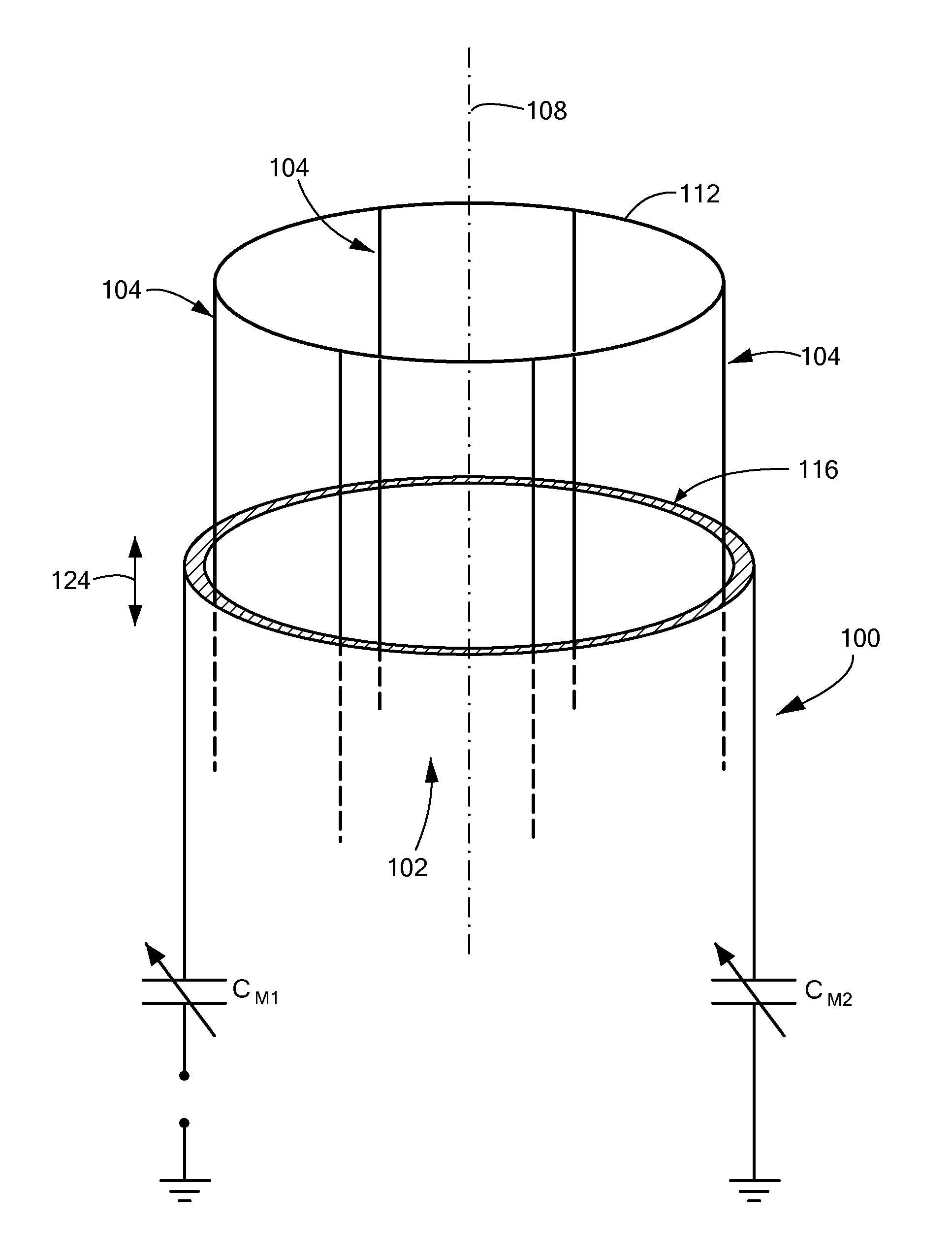
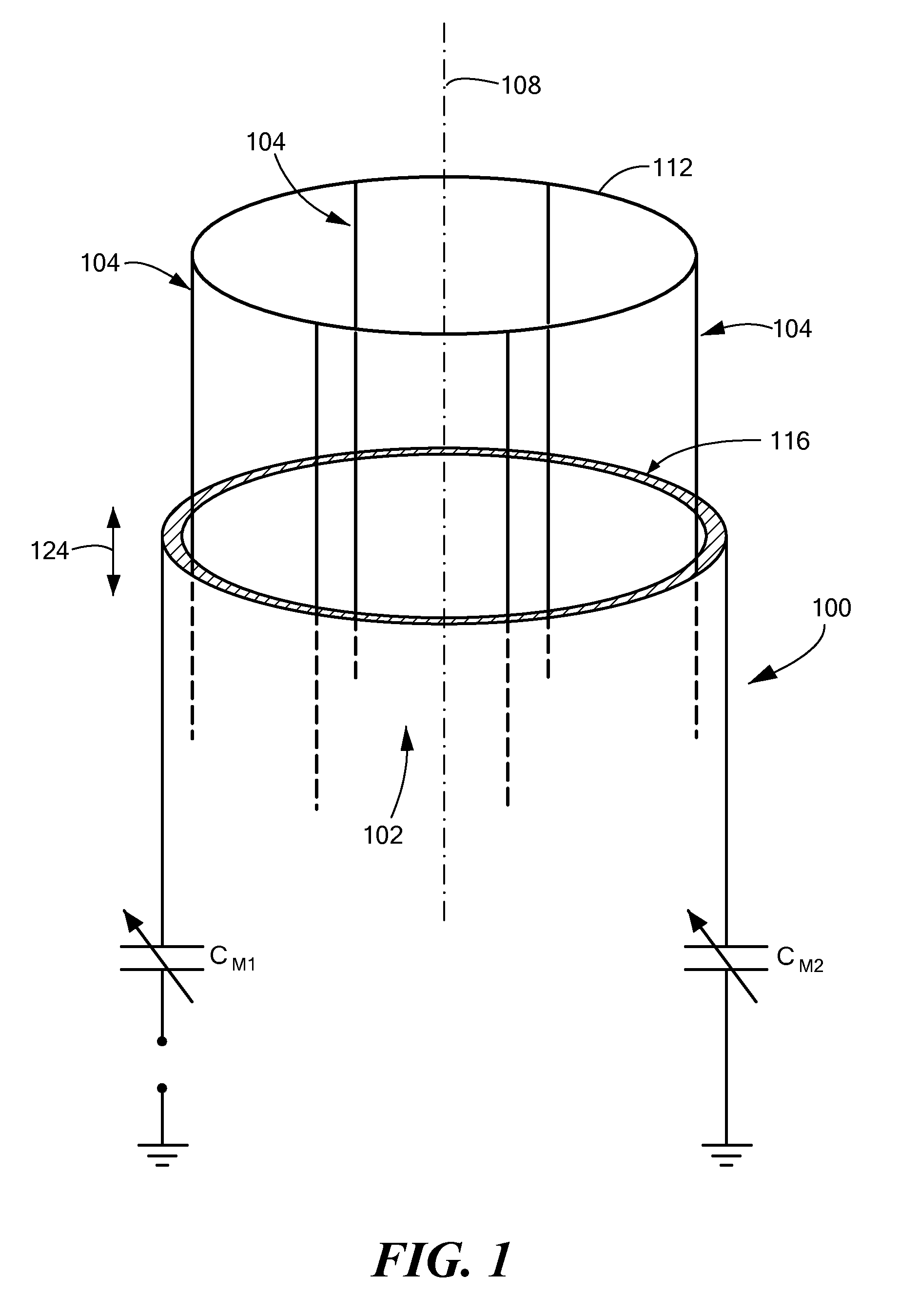
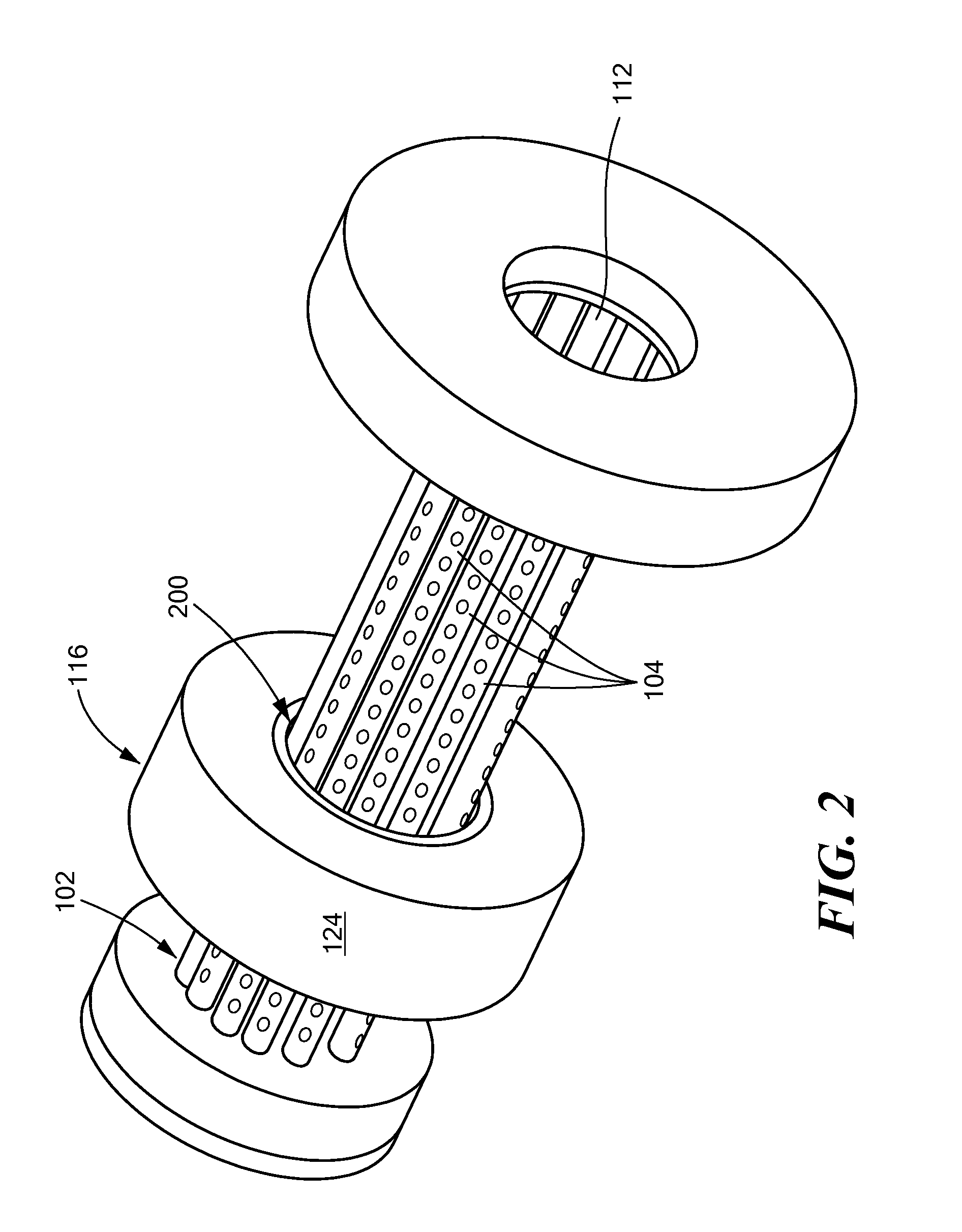
[0028]Embodiments of the invention are based on the empirical finding that a Q-factor and homogeneity of the magnetic field inside the coil, as well as the tuning range, depend on a degree of symmetry of the electrical configuration of the RF-coil circuit and the ability to maintain such symmetry during the coil tuning procedure. Referring now to FIGS. 1 and 2, FIG. 1 shows, in side view, an embodiment of the electrical schematic 100 of the RF coil for use in a magnetic resonance apparatus, while FIG. 2 presents a perspective view of a physical model corresponding ...


PUM


Abstract

A radio frequency (RF) coil comprising a plurality of electrically uninterrupted conductive legs, each leg having a first end and a second end, and at least one continuous conductor electrically connected to the first ends of the legs. Frequency tuning of the coil is achieved by translating, along the legs, an electrically continuous tuning band that includes a capacitor closed about the axis of the coil in proximity to the conductive legs. Maintaining electrical symmetry of the coil results in tuning ranges of at least 30 percent of the nominal value of the resonant frequency.

Description

[0001]The present application claims priority from U.S. Provisional Application No. 61 / 081,954, filed Jul. 18, 2008, the full disclosure of which is hereby incorporated by reference herein.TECHNICAL FIELD[0002]The present invention relates to tunable radiofrequency (RF) coils such as may be used in magnetic resonance imaging (MRI) and nuclear magnetic resonance (NMR) systems, and, more particularly, to RF coils having wide tuning ranges.BACKGROUND ART[0003]RF coils play a crucial role in defining the spatial resolution of imaging systems, serving both to transmit excitatory RF signals to the tissues being interrogated and to collect the returning RF-signal information from the body. Magnetic resonance (MR) RF coils are essentially tuned inductors serving as antennae for the transmission or reception of RF signals.[0004]RF coils are typically classified into two broad categories, volume coils and surface coils, differing in their reception characteristics and used in different imagin...

Claims


Application Information

Patent Timeline
IPC IPC(8): G01R33/44
CPCG01R33/34046G01R33/3628G01R33/3453G01R33/34076
Inventor ODINTSOV, BORIS
Owner THE BOARD OF TRUSTEES OF THE UNIV OF ILLINOIS
Learn More