Electromagnet with adjusting screw

a technology of adjusting screw and electromagnet, which is applied in the direction of electromagnet, fluid pressure control, core/yoke, etc., can solve the problems of high adjustment pin cost and particularly complex manufacturing of adjustment pins

Inactive Publication Date: 2013-02-07
SVM SCHULTZ VERW
View PDF6 Cites 6 Cited by
  • Summary
  • Abstract
  • Description
  • Claims
  • Application Information

AI Technical Summary

Benefits of technology

The invention is about a new type of adjustment pin for a solenoid. The adjustment pin is made through a cold forming process, which may have slightly less accuracy than metal-cutting machining, but this is compensated in the adjustment process. The use of a cold-formed adjustment pin is advantageous because it can be economically manufactured and used in a pressure control valve. The adjustment pin has a smaller diameter at the beginning, making it easier to insert in the solenoid. The invention also includes a conical section that helps with the insertion of the cylindrical section in the solenoid. Overall, the invention improves the performance and cost-effectiveness of the solenoid.

Problems solved by technology

Solenoids of this kind are often part of a complex operating device.
The procedure described before requires a multiple moving of the component to be worked, so that the manufacturing of the adjustment pin is particularly complex.
The result is high costs for the adjustment pin, that is generally a mass product, as suitable solenoids cannot be produced without adjustment pins of this type.

Method used


Image

  • Electromagnet with adjusting screw
  • Electromagnet with adjusting screw
  • Electromagnet with adjusting screw

Examples


Embodiment Construction

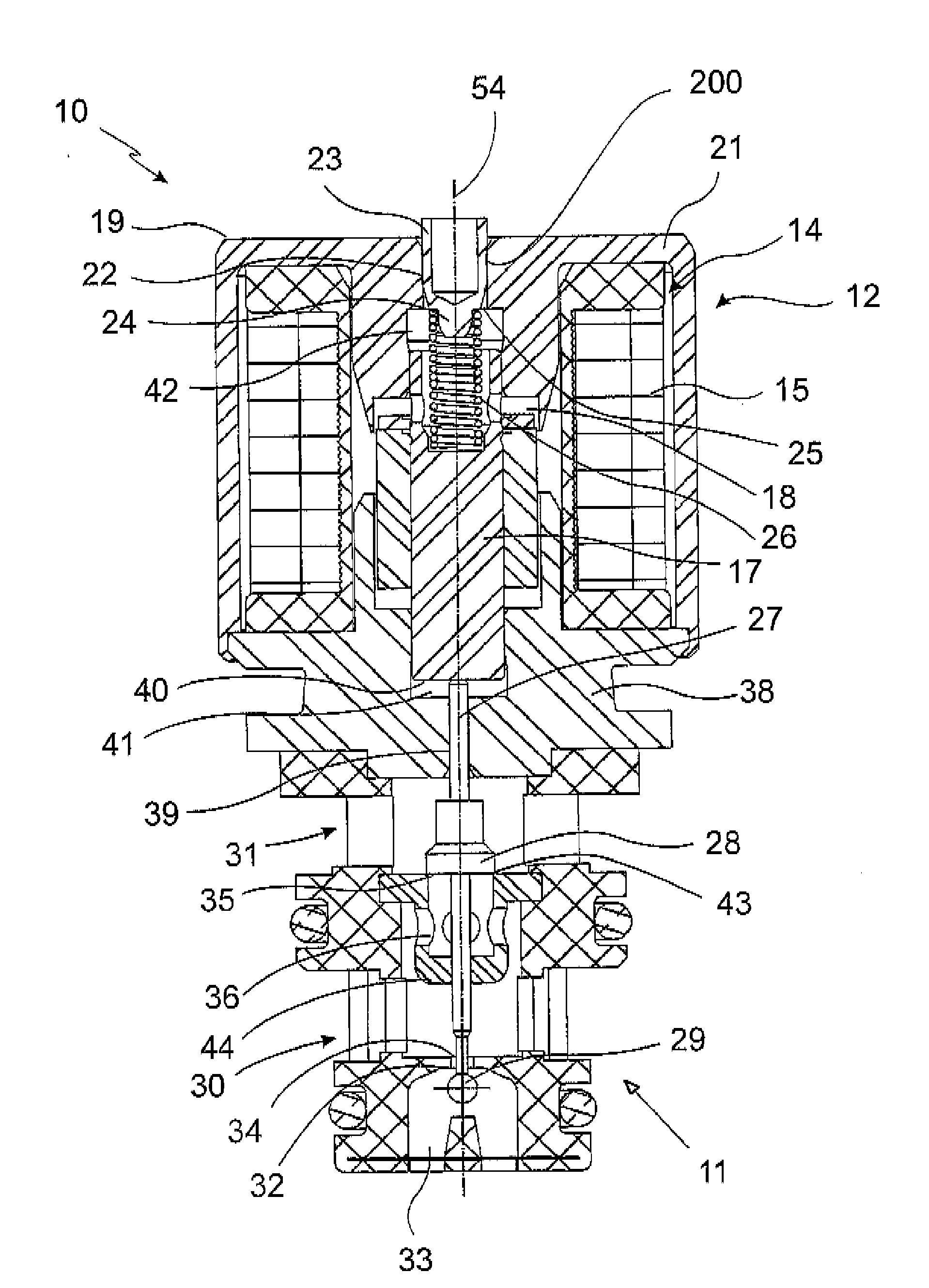
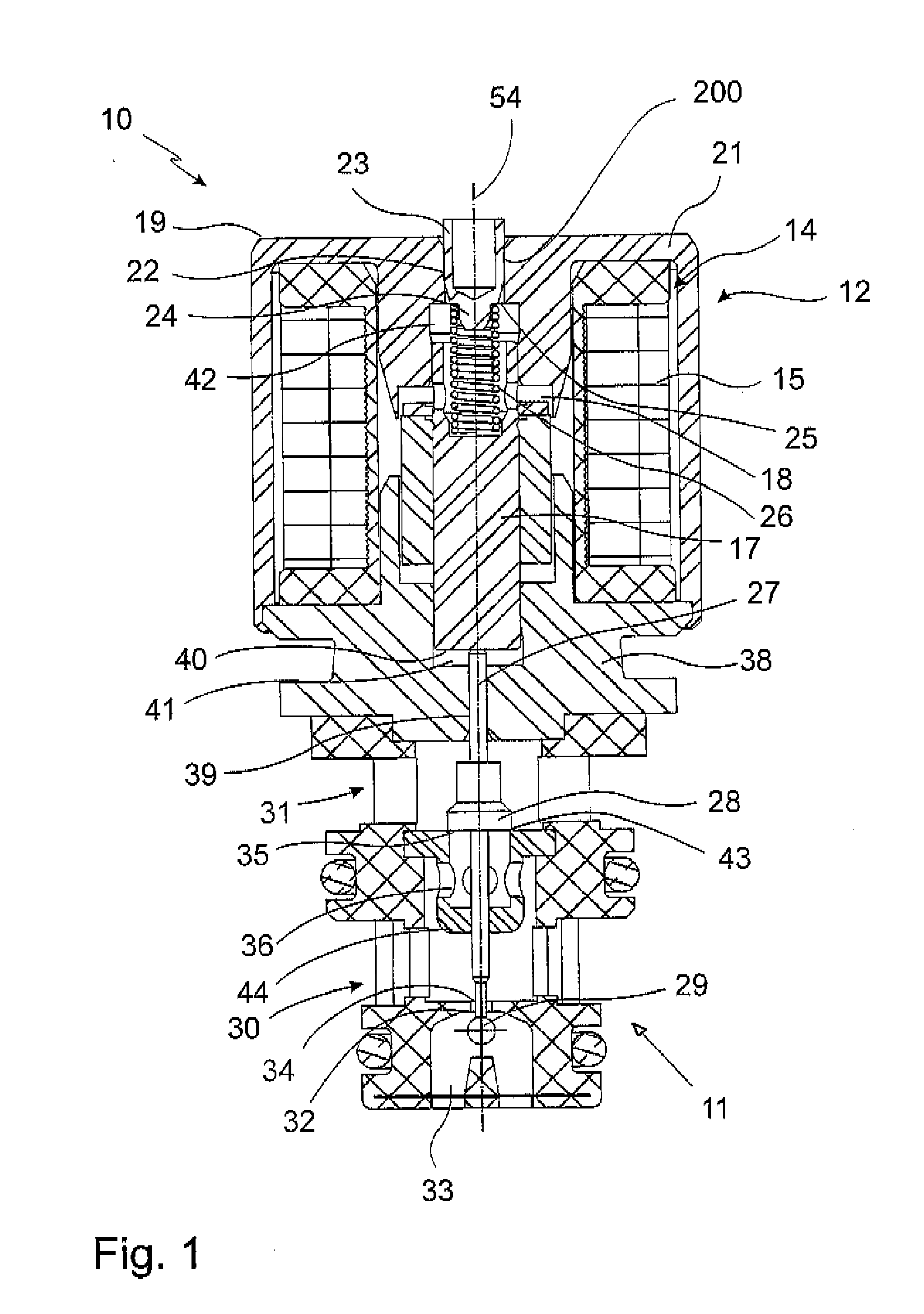
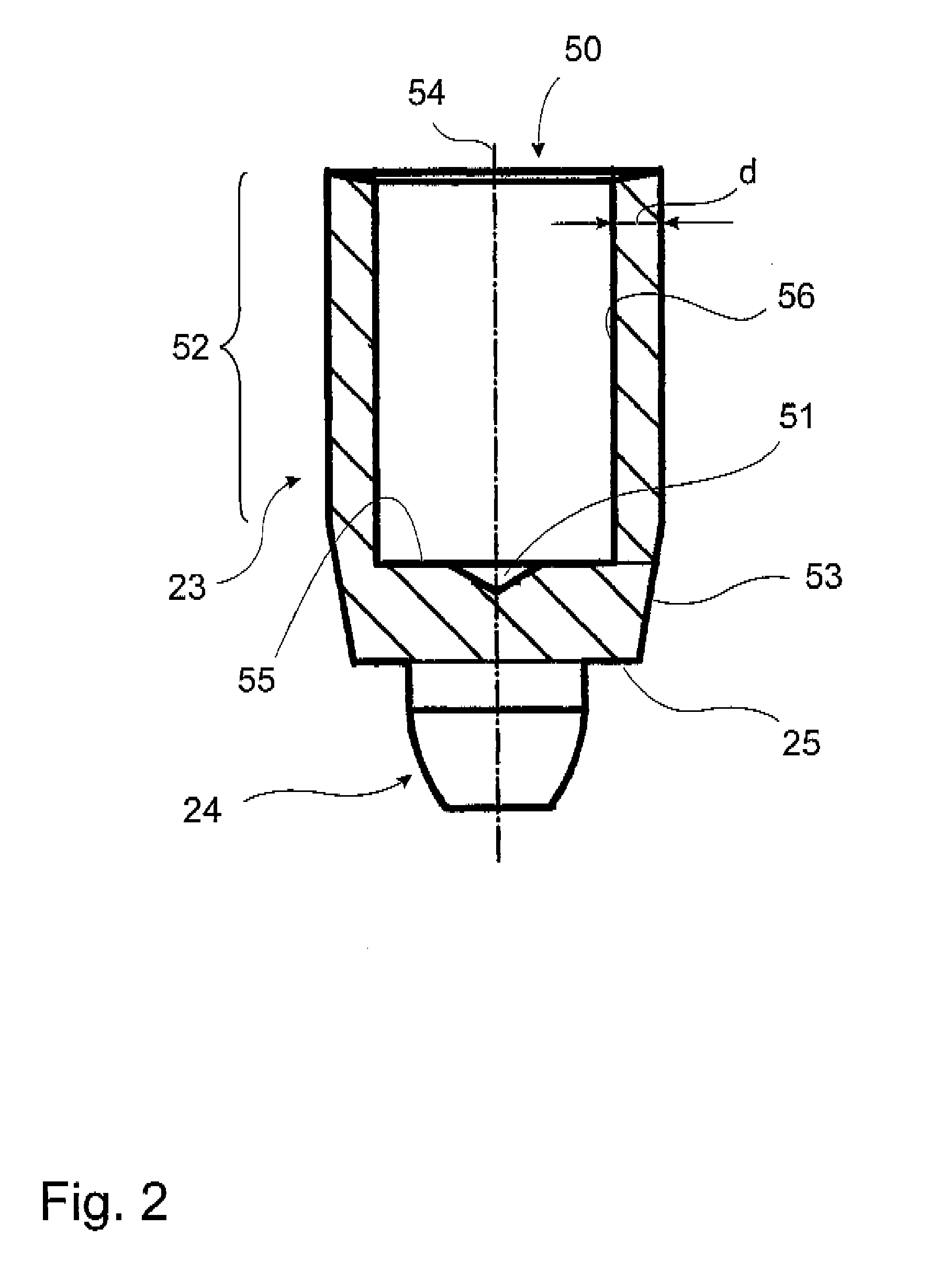
[0025]FIG. 1 shows an optional embodiment of an electro-magnetic pressure control valve 10, consisting of a valve part 11 and a magnetic part 12 arranged coaxially thereto. The magnetic part 12 has a coil body with a coil 15. In the coil body 14 an armature 17 is supported movably in an armature housing 18. On the upper side 19 of the magnetic part 12 a (not shown) connector housing is linked through which the coil 15 can be supplied with current. In the yoke 21 of the magnetic part 12 a recess 22 is located in which an adjustment pin 23 is inserted. The yoke 21 rests on the side of the armature 17 opposite the valve part 11. Thus also the adjustment pin 23 and the armature spring 26 are located on the side of the armature 17 opposite the valve part 11. The adjustment pin 23 is held in a recess 22 in a press fit 200. The adjustment pin 23 has a projecting nose 24, besides, the adjustment pin 23 has a shoulder 25 supporting an armature spring 26. On its opposite end, the armature spr...


PUM

PropertyMeasurementUnit
Thicknessaaaaaaaaaa
Diameteraaaaaaaaaa
Magnetic fieldaaaaaaaaaa

Abstract

The invention refers to a solenoid with a coil that can be supplied with current, an armature supported movably in an armature housing that can be moved by a magnetic field resulting from supplying the coil with current, a magnetic yoke, an armature spring and an adjustment pin that can be inserted in the magnetic yoke, wherein the armature spring is supported, on the one hand, on the adjustment spring, and, on the other hand, on the armature, and the characteristic line of the solenoid can be adjusted through penetration depth of the adjustment pin in the magnetic yoke or the solenoid.

Description

BACKGROUND OF THE INVENTION[0001]The invention refers to a solenoid with a coil, a magnetic yoke, an armature housing, an armature supported movably in the armature housing, an armature spring and an adjustment pin that can be put in the magnetic yoke.[0002]Solenoids of this kind are often part of a complex operating device. By means of the solenoid, different conditions of the operative device are set, for example a locking is generated or a pressure valve or pressure control valve is operated. The solenoid has a coil that can be supplied with current. When current flows through, the result is a magnetic field acting usually against the power of an (armature) spring on a magnetizable armature that is arranged movably in the armature housing of the solenoid. The armature moves depending on the resulting magnetic field.[0003]So-called proportional magnets or proportional solenoids have been known as well, where the position of the armature (and thus also the position of the element m...

Claims


Application Information

Patent Timeline
IPC IPC(8): H01F7/126F16K31/02H01F41/00
CPCH01F7/13Y10T29/4902H01F2007/086H01F7/1607F16K31/0675G05D16/2024H01F7/127
Inventor SCHERER, GEORGMANG, HELMUTSCHREIBER, FLORIAN
Owner SVM SCHULTZ VERW
Why Eureka
Try Eureka