Method of analyzing reflection waves using effective impedance

a reflection wave and effective impedance technology, applied in the direction of material impedance, transmission monitoring, instruments, etc., can solve the problems of inconvenient application of radio wave propagation models, ray tracking schemes that need take such a long time to perform simulations, etc., to achieve easy modeling, reduce unnecessary calculation processes and calculation time, and reduce computation amount for radio wave modeling

Inactive Publication Date: 2010-01-14
ELECTRONICS & TELECOMM RES INST
View PDF3 Cites 1 Cited by
  • Summary
  • Abstract
  • Description
  • Claims
  • Application Information

AI Technical Summary

Benefits of technology

[0020]Since the radio wave model created using effective impedance according to the present embodiment exactly matches with real radio wave and the reflection wave of non-uniform medium can be replaced with the reflection wave, the computation amount for the radio wave modeling is significantly reduced according to an embodiment of the present invention. Therefore, a radio wave can be easily modeled according to an embodiment of the present invention.
[0021]According to an embodiment of the present invention, unnecessary calculation processes and a calculation time can be reduced by uniquely defining impedance that influences to a reflection wave generated from a reflection surface when a radio wave model of a ray tracing method is used through simply changing a reflection surface made of complex materials to a reflection surface made of single material having the same electrical character and using the defined impedance for a single surface. Therefore, the load of a base station can be reduced.

Problems solved by technology

Therefore, it is not proper to apply a radio wave propagation model for macrocell to a microcell, and a new radio wave propagation model is required for the radio wave propagation environment for the microcell.
However, the ray tracking scheme needs such a long time to perform simulation.
Since the ray shooting method and the ray tube method search all of propagation paths including propagation paths reaching a receiver and propagation paths not reaching the receiver, it takes such a long time to perform a simulation.
It is an annoying process.
Therefore, the computation amount thereof and the load of a base station increase.

Method used


Image

  • Method of analyzing reflection waves using effective impedance
  • Method of analyzing reflection waves using effective impedance
  • Method of analyzing reflection waves using effective impedance

Examples


Embodiment Construction

[0027]Reference will now be made in detail to the preferred embodiments of the present invention, examples of which are illustrated in the accompanying drawings.

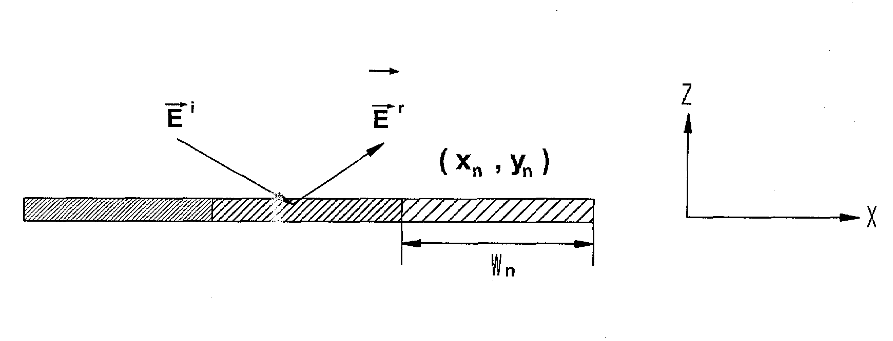
[0028]FIG. 1 is a diagram illustrating a reflection surface of a building two-dimensionally according to an embodiment of the present invention.

[0029]Referring to FIG. 1, since reflection surfaces of buildings have similar structural characteristics in a vertical direction, the reflection surfaces can be simply modeled two-dimensionally as shown in FIG. 1. Although the reflection surfaces of buildings are modeled as a horizontal surface, the reflection surface of buildings can be modeled as a vertical surface as well as the horizontal surface.

[0030]At first, a transmitter 10 outputs an electric field

{right arrow over (E)}i

and a magnetic field

{right arrow over (H)}i

and a receiver 20 receives the electric field

{right arrow over (E)}r

and a magnetic field

{right arrow over (H)}r

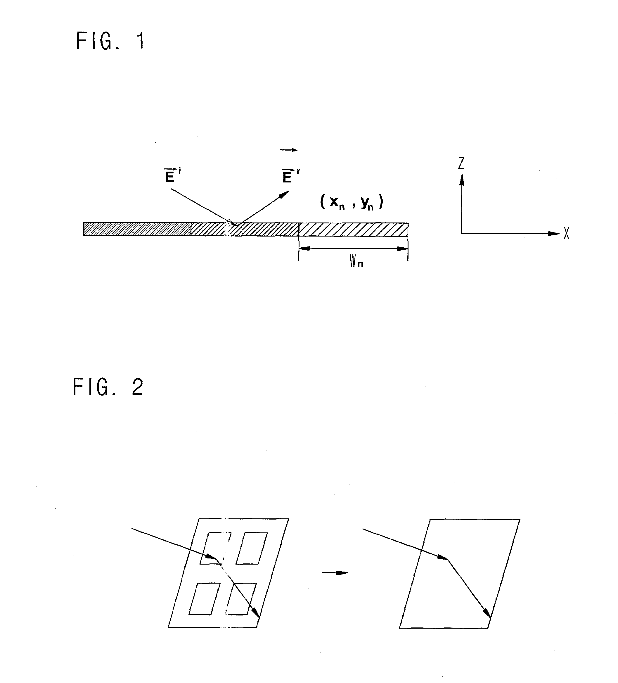
[0031]In order to consider the non-uniform mediu...


PUM


Abstract

Provided is a method for analyzing a reflection wave using effective impedance. The method includes the steps of: a) modeling a reflection surface of a building two-dimensionally; and b) obtaining a reflection wave by radiating a radio wave to the modeled reflection surface and analyzing the obtained reflection wave through making medium uniform.

Description

TECHNICAL FIELD[0001]The present invention relates to a method for analyzing reflection waves using effective impedance, and more particularly, to a method for analyzing reflection waves using effective impedance that effectively transform electric characteristics such as impedance under assumption that a reflection surface propagating a radio wave is made of single material although the reflection surface is made of complex materials.BACKGROUND ART[0002]Recently, there are many researches about a micro cell and a pico cell in actively progress for accommodating more subscribers with limited frequency resources as the demand of mobile communication has abruptly increased.[0003]In order to increase capacity and improve speech quality according to the increment of demand for the wireless communication, wireless communication technology has been gradually advanced to a micro cell or a pico cell based wireless communication technology.[0004]A microcell is a cell having a very small cove...

Claims


Application Information

Patent Timeline
Patent Type & Authority Applications(United States)
IPC IPC(8): G01R13/00
CPCH04B17/3912G01N3/00G01N27/00G01N27/02
Inventor KIM, JONG HOHONG, HEON JINKIM, CHANG JOOKOH, IL SUEKLIM, JAE WOO
Owner ELECTRONICS & TELECOMM RES INST
Why Eureka
Try Eureka