
Deployable Arc Fusion Cage and Methods Associated Therewith

a fusion cage and arc technology, applied in the field of expandable fusion cages and methods, can solve the problems of large insertion slots, difficult to re-inject the device, and difficulty in re-injecting the device, so as to facilitate the insertion and manipulation of the device, and facilitate the healing of the patient.

Inactive Publication Date: 2010-01-14
KYPHON
View PDF21 Cites 65 Cited by
  • Summary
  • Abstract
  • Description
  • Claims
  • Application Information

AI Technical Summary

Benefits of technology

[0012]The present invention relates to expandable fusion cages that can be inserted into adjacent vertebrae in an unexpanded state and can then be expanded. The fusion cages of the present invention are designed and configured so as to be readily inserted, accessible, and manipulated by non-invasive means. Moreover, in several of the embodiments of the present invention, the fusion cages are designed so as to allow the incorporation of other materials that will facilitate the insertion and manipulation of the device as well as the healing of the patient.

Problems solved by technology

The device disclosed in the Larsen reference has several problems.
One problem is that, because the width of the implant is adjusted prior to insertion, a wide insertion slot is necessary despite the reduced profile presented by the collapsed implant.
Accordingly, insertion of the cage using non-invasive means such as through the use of a cannula tends to be somewhat limited.
Another problem is that at least part of the linkage mechanism extends beyond the upper and lower plate portions, thus requiring more invasion into the body cavity to position the implant.
Brett, U.S. Pat. No. 6,126,689, illustrates an expandable and collapsible fusion cage, but its design uses hinges on two sides of the fusion cage, which makes its operation unwieldy.
Moreover, the fusion cage can be difficult to expand when it is in the disk space, particularly in the instance wherein one desires non-invasive surgical techniques such as access to the spine using cannulas.
Moreover, the fusion cage of Brett has only limited expanded state possibilities so that it is either in a fully expanded state or an intermediate partially expanded state.

Method used


Image

  • Deployable Arc Fusion Cage and Methods Associated Therewith
  • Deployable Arc Fusion Cage and Methods Associated Therewith
  • Deployable Arc Fusion Cage and Methods Associated Therewith

Examples


Embodiment Construction

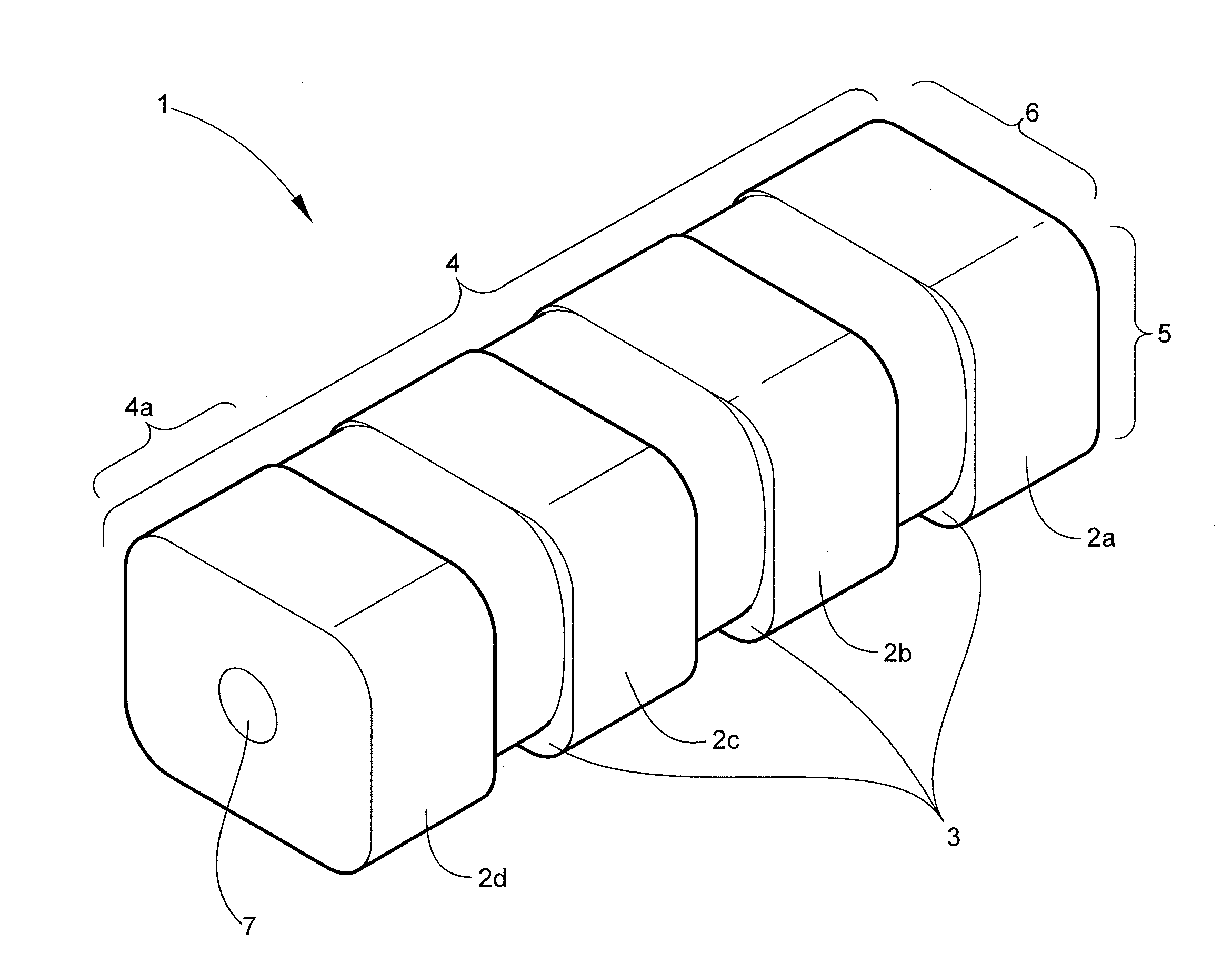
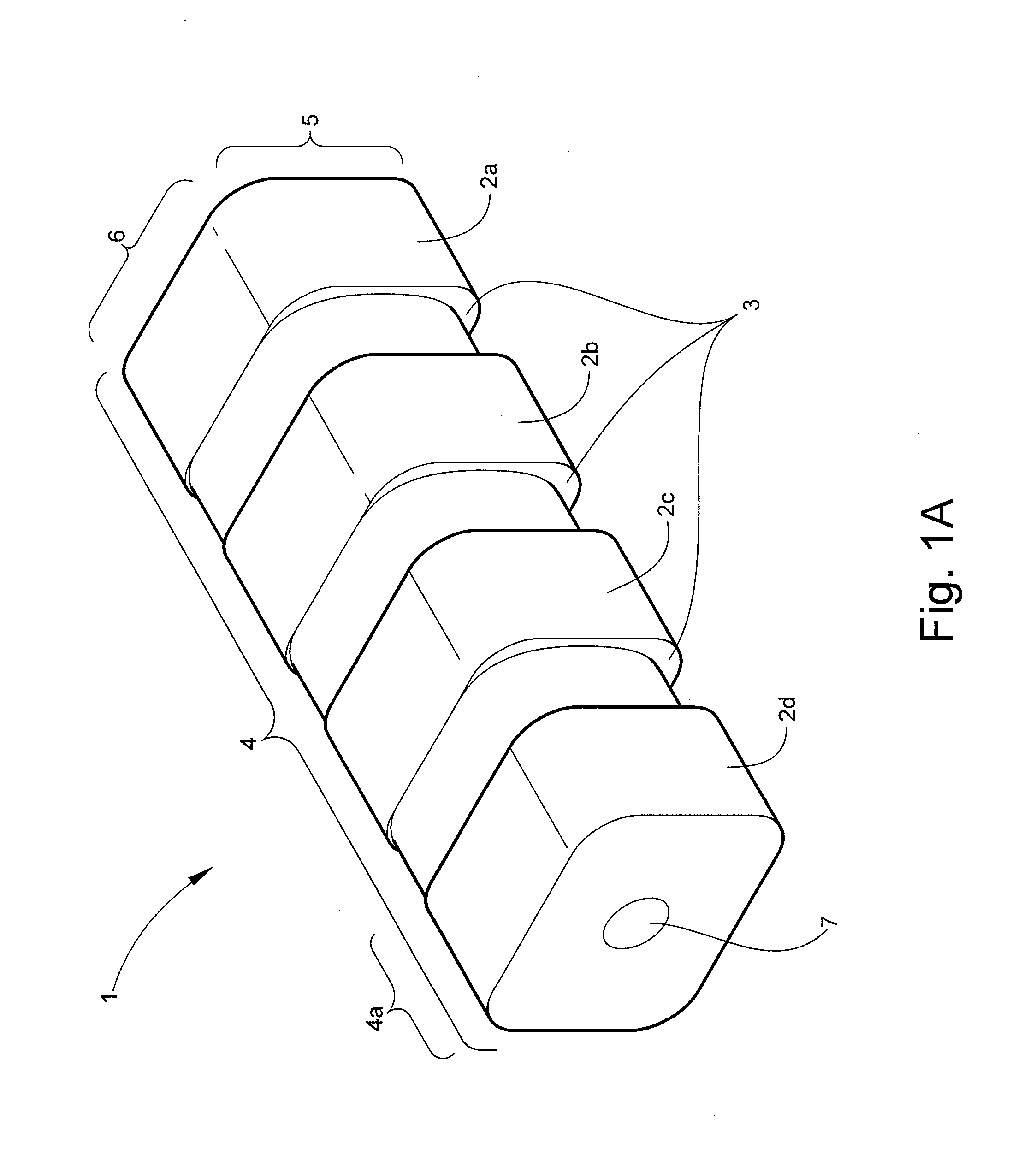
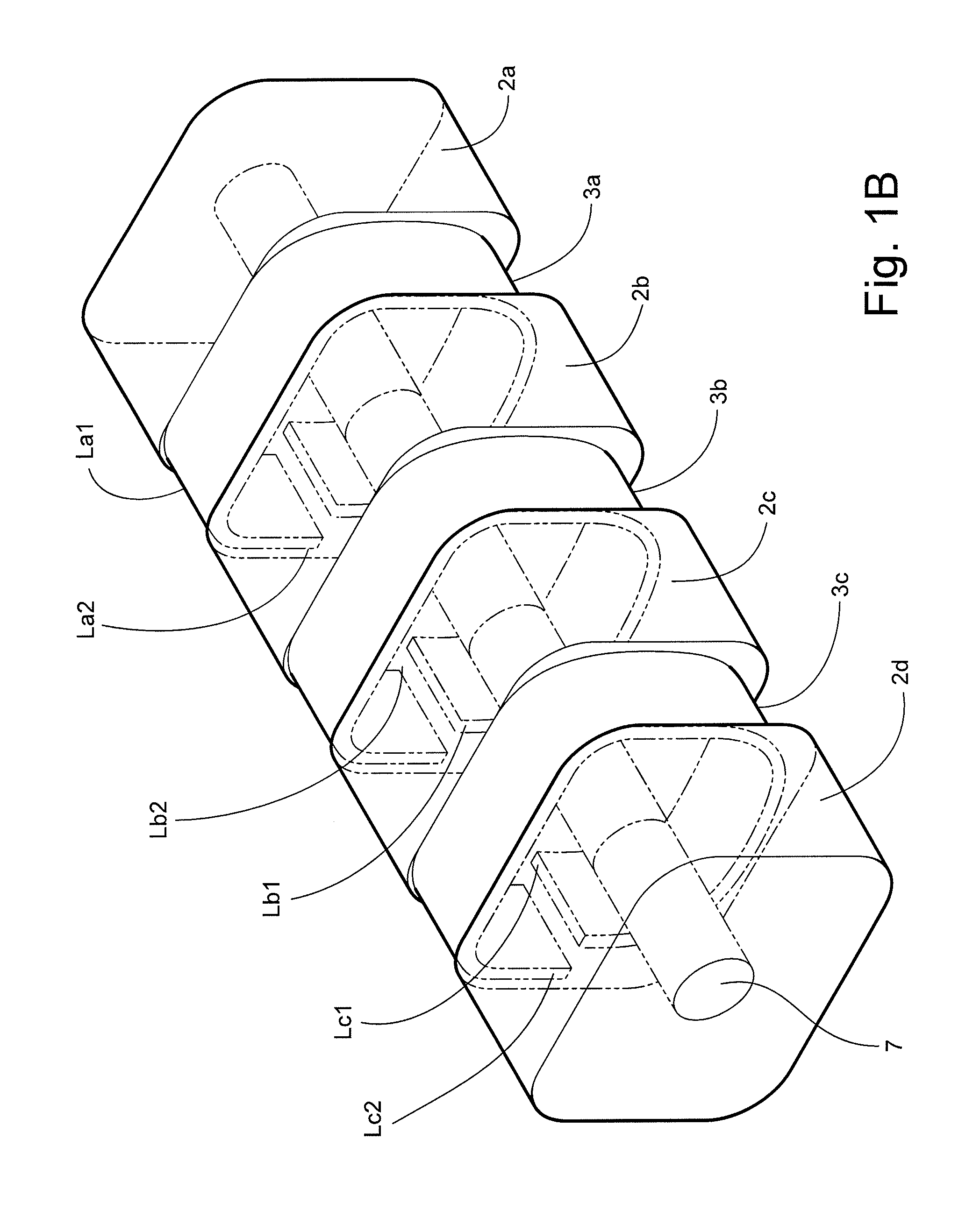
[0020]In an embodiment, the present invention relates to expandable fusion cages and methods associated therewith. The present invention generally relates to an apparatus and method for implanting an anterior installed intervertebral fusion cage system which can be selectively expanded between two adjacent vertebrae to cause them to change and hold their position relative to each other and produce a normal alignment of the spine, while promoting fusion of the vertebrae. The invention also relates to an expandable fusion cage that may be inserted, in a reduced size configuration, into an intervertebral space and expanded after insertion to provide a desired size.

[0021]An embodiment of the present invention relates to an expandable fusion cage comprising spacers and one or more deployable extensions (also called a “flexible element”), wherein the one or more deployable extensions are configured so that each deployable extension alternates with each spacer and the deployable extensions...


PUM

PropertyMeasurementUnit
Lengthaaaaaaaaaa
Lengthaaaaaaaaaa
Angleaaaaaaaaaa

Abstract

Expandable fusion cages and methods associated therewith are disclosed. The present invention is generally directed to an apparatus and method for implanting an anterior installed intervertebral fusion cage system which can be selectively expanded between two adjacent vertebrae to cause them to change position relative to each other and produce a normal alignment of the spine, while promoting fusion of the vertebrae. Accordingly, the invention relates to an expandable fusion cage that may be inserted, in a reduced size configuration, into an intervertebral space and expanded after insertion to provide a desired size.

Description

FIELD OF THE INVENTION[0001]The present invention relates to expandable fusion cages and methods associated therewith. Moreover, the present invention is generally directed to an apparatus and method for implanting an anterior installed intervertebral fusion cage system which can be selectively expanded between two adjacent vertebrae to cause them to change position relative to each other and produce a normal alignment of the spine, while promoting fusion of the vertebrae. The invention also relates to an expandable fusion cage that may be inserted, in a reduced size configuration, into an intervertebral space and expanded after insertion to provide a desired size.BACKGROUND OF THE INVENTION[0002]Spinal implants can either be solid, sometimes referred to as a spacer or plug, or can define a hollow interior designed to permit bone in-growth, sometimes referred to as a fusion device or fusion cage. The interior of a fusion device may be filled with a bone growth inducing substance to ...

Claims


Application Information

Patent Timeline
IPC IPC(8): A61F2/44
CPCA61F2/447A61F2310/00293A61F2002/2835A61F2002/30014A61F2002/30018A61F2002/30062A61F2002/30092A61F2002/30113A61F2002/30125A61F2002/30131A61F2002/30153A61F2002/30156A61F2002/30171A61F2002/30355A61F2002/30472A61F2002/30481A61F2002/30484A61F2002/30497A61F2002/30546A61F2002/30579A61F2002/30607A61F2002/30616A61F2002/30726A61F2002/4415A61F2002/448A61F2002/4631A61F2210/0004A61F2210/0014A61F2220/0025A61F2220/0033A61F2220/0041A61F2230/0006A61F2230/0008A61F2230/0013A61F2230/0019A61F2230/0023A61F2230/005A61F2250/0012A61F2250/0018A61F2250/0029A61F2250/0062A61F2310/00017A61F2310/00023A61F2310/00095A61F2310/00131A61F2310/00149A61F2/4611A61F2002/30433A61F2002/30495
Inventor KOHM, ANDREW
Owner KYPHON
Learn More