
Wavelength selective switch using planar lightwave circuit technology

a planar lightwave circuit and selective switch technology, applied in the field of wavelength selective switch, can solve the problems of complex fabrication process technology, and achieve the effect of simple structure, reduced the number of wavelength division multiplexers, and simplified fabrication process technology

Inactive Publication Date: 2010-01-14
ELECTRONICS & TELECOMM RES INST
View PDF6 Cites 1 Cited by
  • Summary
  • Abstract
  • Description
  • Claims
  • Application Information

AI Technical Summary

Benefits of technology

[0008]The present invention provides a wavelength selective switch having a simple structure which minimizes the number of wavelength division multiplexers in which technical implementation is difficult and fabricating costs expensive and a method for fabricating the same.

Problems solved by technology

Also, the complex fabrication process technology is required due to difficult wavelength tuning and a high defect rate.

Method used


Image

  • Wavelength selective switch using planar lightwave circuit technology
  • Wavelength selective switch using planar lightwave circuit technology
  • Wavelength selective switch using planar lightwave circuit technology

Examples


Embodiment Construction

[0028]Preferred embodiments of the present invention will be described below in more detail with reference to the accompanying drawings so that this disclosure will be thorough and complete, and will fully convey the scope of the present invention to those skilled in the art.

[0029]A wavelength selective switch using a planar lightwave circuit technology according to the present invention includes only two wavelength division multiplexers. Thus, the wavelength selective switch can increase reliability of a switching operation and reduce an occupation area as well as manufacturing costs.

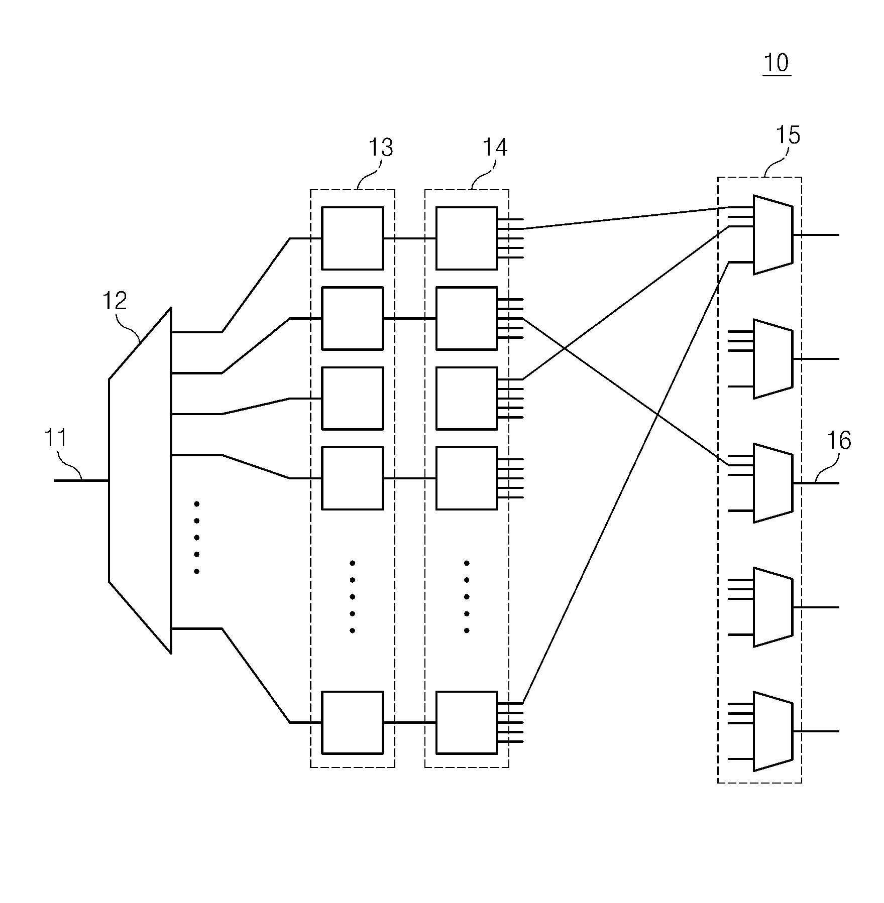
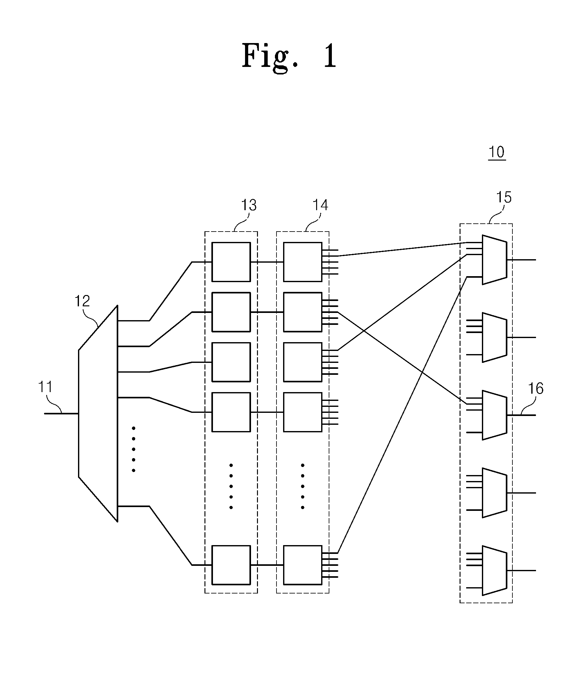
[0030]FIG. 2 is a view of a wavelength selective switch 100 according to an embodiment of the present invention. Referring to FIG. 2, the wavelength selective switch 100 includes a first wavelength division multiplexer 110, a switch array 120, optical combiners 131, 132, . . . , and 13K, and a second wavelength division multiplexer 140. An optical signal progresses as described below.

[0031]Optical sign...


PUM

PropertyMeasurementUnit
wavelength selectiveaaaaaaaaaa
wavelength spacingaaaaaaaaaa
channel wavelengthaaaaaaaaaa

Abstract

Provided is a wavelength selective switch. The wavelength selective switch includes a first wavelength division multiplexer, an M number of optical switches, an (M+N−1) number of optical combiners, and a second wavelength division multiplexer. The first wavelength division multiplexer receives optical signals of an M number of wavelength channels to divide the received optical signals according to each channel, thereby outputting the divided optical signals. The M number of optical switches changes a path of on an optical signal outputted by an M number of wavelength channels from the first wavelength division multiplexer into one of an N number of output ports. The (M+N−1) number of optical combiners is respectively connected to the N number of output ports of the optical switches. The (M+N−1) number of optical combiners couple the N number of inputted optical signals to one output port. The second wavelength division multiplexer has an (M+N−1) number of input ports and an N number of output ports. The (M+N−1) number of output signals of the optical combiners is connected to the input ports, respectively, and the inputted signals are multiplexed to output the multiplexed signals from any of the N number of output ports.

Description

CROSS-REFERENCE TO RELATED APPLICATIONS[0001]This U.S. non-provisional patent application claims priority under 35 U.S.C. §119 of Korean Patent Application No. 10-2008-0066470, filed on Jul. 9, 2008, the entire contents of which are hereby incorporated by reference.BACKGROUND OF THE INVENTION[0002]The present invention disclosed herein relates to a wavelength selective switch used in a wavelength division multiplexing optical transmission system for simultaneously transmitting optical signals of different optical wavelengths, and more particularly, to a wavelength selective switch that can be simply realized through a planar lightwave circuit technology.[0003]A wavelength selective switch is a switch that can selectively connect an arbitrary optical channel (corresponding to an arbitrary wavelength) with an arbitrary input / output port in a wavelength division multiplexing optical transmission system, where a plurality of optical channels with different wavelengths are transmitted th...

Claims


Application Information

Patent Timeline
Patent Type & Authority Applications(United States)
IPC IPC(8): H04J14/08G02B6/12G02F1/01G02F1/313H04B10/2581
CPCH04Q11/0005H04Q2011/0052H04Q2011/0035H04Q2011/0016
Inventor SHIN, JANG-UKHAN, YOUNG-TAKHAN, SANG-PILPARK, SANG-HOBAEK, YONGSOON
Owner ELECTRONICS & TELECOMM RES INST
Learn More