
Electromagnetic heating

a technology of electromagnetic heating and heat dissipation, applied in the field of electromagnetic heating, can solve the problems of limited ability to achieve uniform heating, many problems in the prior art, inadequate measures taken by prior art investigators to provide uniform heating, etc., to achieve the effect of improving the net power and/or efficiency and/or uniformity of energy transfer, reducing the cost of heating equipment, and increasing the flexibility of providing power

Active Publication Date: 2010-01-14
JOLIET 2010 LTD
View PDF106 Cites 32 Cited by
  • Summary
  • Abstract
  • Description
  • Claims
  • Application Information

AI Technical Summary

Benefits of technology

This approach achieves uniform heating with temperature variations of less than 50°C across the object, improving efficiency and preventing hotspots, enabling effective defrosting and cooking of irregularly shaped items without recrystallization or damage.

Problems solved by technology

The present inventors have realized that the measures taken by prior art investigators to provide uniform heating were inadequate and could not, by themselves, lead to a viable methodology for uniform heating (or defrosting) of irregular shaped objects such as organs, foods or the like.
In particular it was discovered that the prior art suffered from many problems.
The inventors realized that the constraints of using a substantially constant frequency, or even tracking a single dissipation peak in a small frequency range, significantly limited the ability to achieve uniform heating.
The inventors also found that the structure of the cavity of a conventional microwave oven, and especially the mode structure of the cavity, inherently did not allow achievement of uniform heating.

Method used

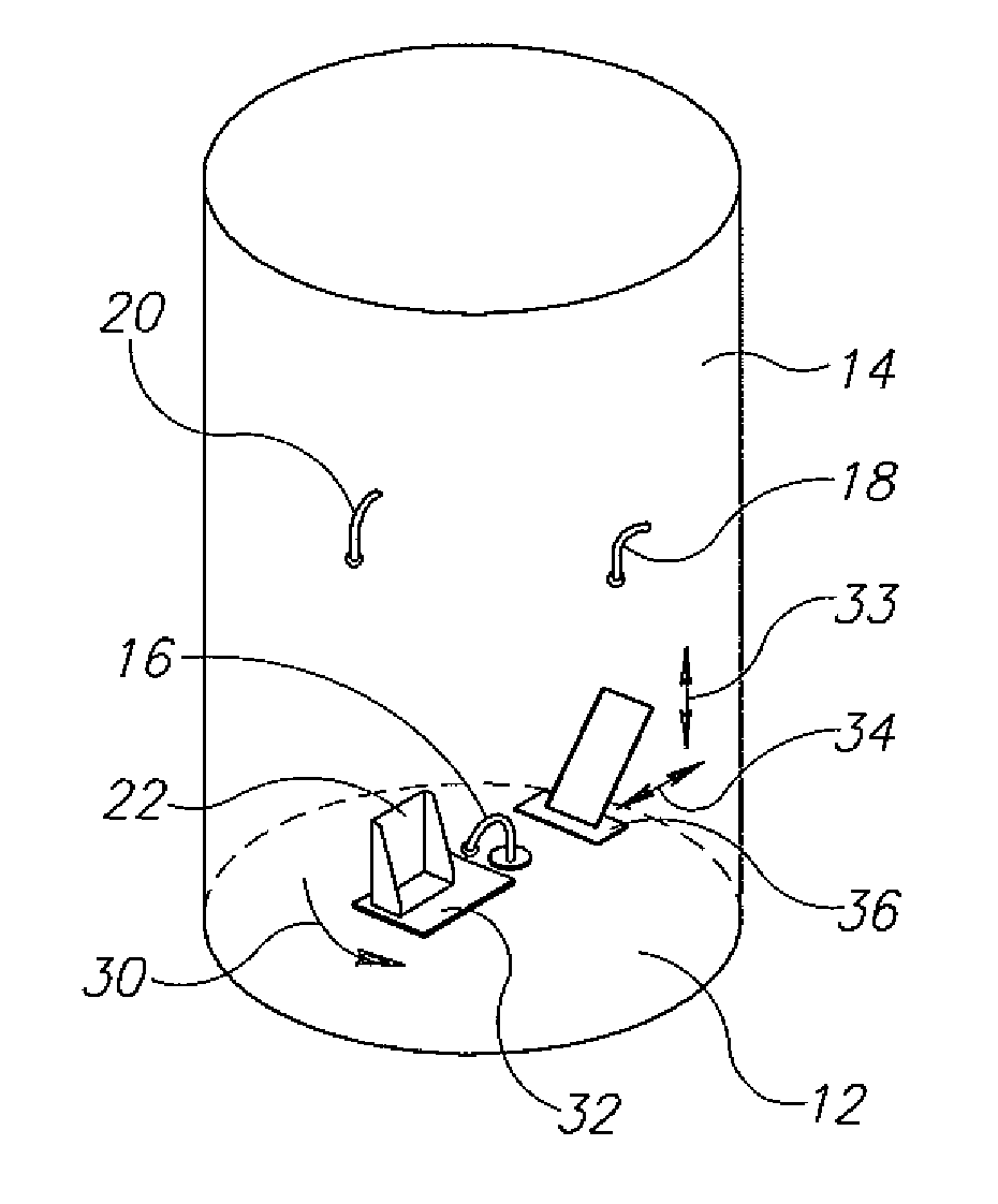
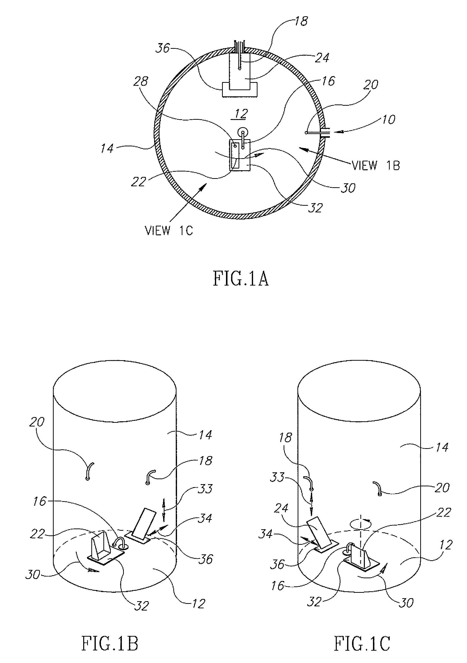
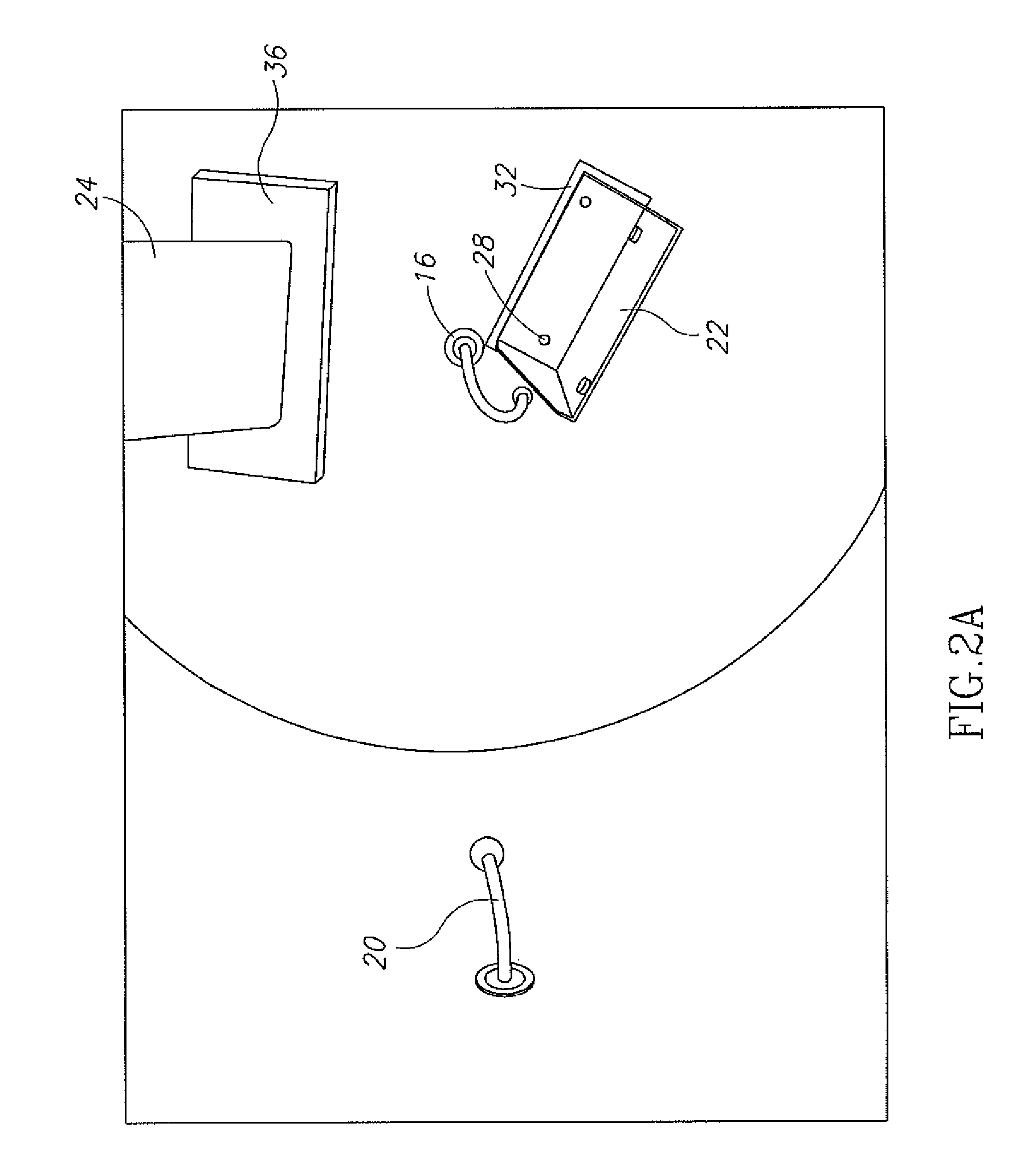

Image

  • Electromagnetic heating
  • Electromagnetic heating
  • Electromagnetic heating

Examples


first embodiment

[0283]In the invention, the maximum net power efficiency for each port is maximized, in the sense, that the net power efficiency at a point of maximum efficiency within the sweep range is made as high as possible. The efficiency and the frequency at which the efficiency is a maximum is noted. Optionally, the width of the efficiency peak and a Q-factor are noted as well.

second embodiment

[0284]the invention is based on a similar criterion. For this embodiment the area under each resonance peak of the net efficiency of transfer is determined. This area should be a maximum. The efficiency, the center frequency of the resonance having the maximum area and its width are noted.

[0285]In an embodiment of the invention, the criteria for determining if the variables are properly set is when the peak net efficiency (first embodiment) or the area or a width (second embodiment) is above some predetermined level or a Q-factor is below some predetermined level. For example, there may be a restriction that the area above 60% net efficiency is maximized for each of the feeds.

[0286]It is noted that energy that is neither reflected nor transmitted to the other ports is absorbed either in the walls of the cavity or in the object being heated. Since absorption in the conducting walls is much lower than that in the object by a large factor, the net efficiency is approximated by the prop...


PUM


Abstract

An electromagnetic heater for heating an irregularly shaped object, including:a cavity within which an object is to be placed;at least one feed which feeds UHF or microwave energy into the cavity; anda controller that controls one or more characteristics of the cavity or energy to assure that the UHF or microwave energy is deposited uniformly in the object within ±30% over at least 80% of the volume of the object.

Description

RELATED APPLICATIONS[0001]The present application is a U.S. Continuation Application of U.S. patent application Ser. No. 12 / 222,948, filed on Aug. 20, 2008, which is a U.S. Continuation Patent Application of PCT Patent Application No. PCT / IL2007 / 000236, filed on Feb. 21, 2007, which claims priority of U.S. Provisional Patent Application No. 60 / 775,231, filed on Feb. 21, 2006 and U.S. Provisional Patent Application No. 60 / 806,860, filed on Jul. 10, 2006. The contents of the above-referenced applications are incorporated herein by reference.FIELD OF THE INVENTION[0002]The present invention is concerned generally with heating of materials with electromagnetic energy.BACKGROUND OF THE INVENTION[0003]The microwave oven is a ubiquitous feature in modern society. However, its limitations are well known. These include, for example uneven heating and slow absorption of heat. In fact, ordinary microwave ovens, when used for heating (e.g. defrosting), cause temperature differences as high as 1...

Claims


Application Information

Patent Timeline
Patent Type & Authority Applications(United States)
IPC IPC(8): H05B6/68
CPCH05B6/647H05B6/705Y02B40/146H05B6/666H05B2206/044Y02B40/00H05B6/80F24C7/02
Inventor BEN-SHMUEL, ERANBILCHINSKY, ALEXANDER
Owner JOLIET 2010 LTD
Learn More