
Orthopedic method for correcting angular bone deformity

a technology of angular bone deformation and orthopedic device, which is applied in the field of orthopedic device and method for correcting angular bone deformation, can solve the problems of increased joint arthritis, reduced bone density, and increased joint pain, and achieves the effects of correcting angular deformation, and promoting asymmetric growth of growth pla

Active Publication Date: 2010-01-07
PEGA MEDICAL
View PDF6 Cites 13 Cited by
  • Summary
  • Abstract
  • Description
  • Claims
  • Application Information

AI Technical Summary

Benefits of technology

"The present invention provides an orthopedic device and method for correcting angular deformation of a bone structure. The device includes first and second hinge members that are pivotally connected together at a pivot joint. The first hinge member is adapted for connection to the first bone portion and the second hinge member is adapted for connection to the second bone portion. Alignment of the pivot joint with the growth plate promotes asymmetric growth of the growth plate to thereby correct the angular deformation. The technical effect of the invention is to provide a simple and effective solution for correcting angular deformation of a bone structure."

Problems solved by technology

Either of these conditions in one or both legs may result in improper load distribution on the knee joint, causing swelling, knee pain, loss of stability, subluxation, increased joint arthritis, and other conditions that restrict one's lifestyle.
The depth of the wedge is critical in that if the wedge is too shallow, thus rendering the bridge too wide, the resulting wide fulcrum results in over stressing of the medial cortex during wedge compression, causing fracture of the bone bridge.
If the wedge is too deep (the residual bone bridge is too narrow) the residual bone bridge, if not completely severed, may lack sufficient strength to provide medial stability to the reduced osteotomy.
However, this technique involves destruction of one half of the growth plate and therefore not a viable option for all patients.
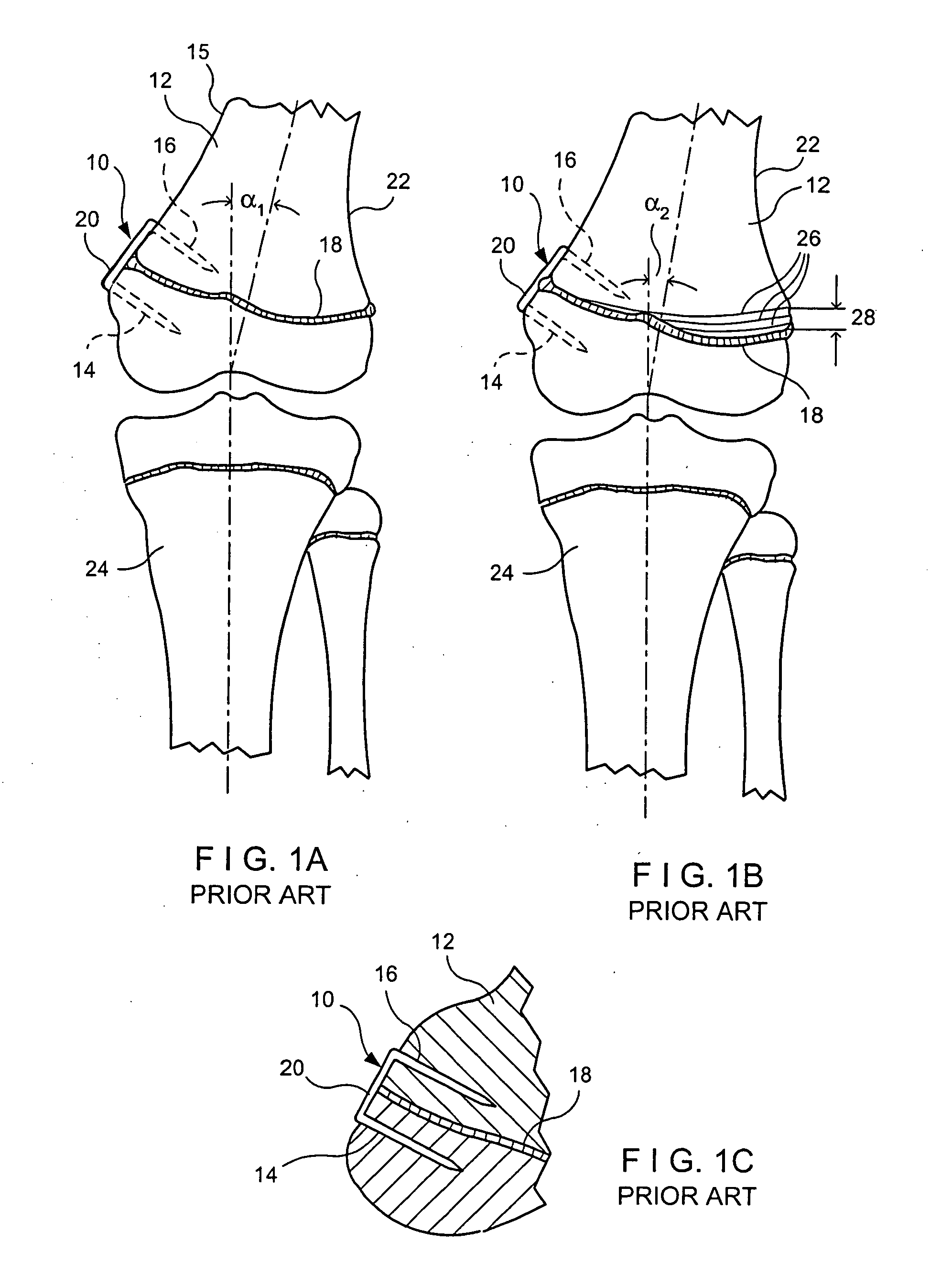
Although hemiepiphyseal stapling is, in some instances, advantageous over other techniques, it suffers from numerous drawbacks.
However, since the staple 10 must have prongs 14, 16 of sufficient length to ensure firm anchorage into the distal femur, more of the physis may be restricted from growth than desired, leading to less bone angle correction.

Method used


Image

  • Orthopedic method for correcting angular bone deformity
  • Orthopedic method for correcting angular bone deformity
  • Orthopedic method for correcting angular bone deformity

Examples


Embodiment Construction

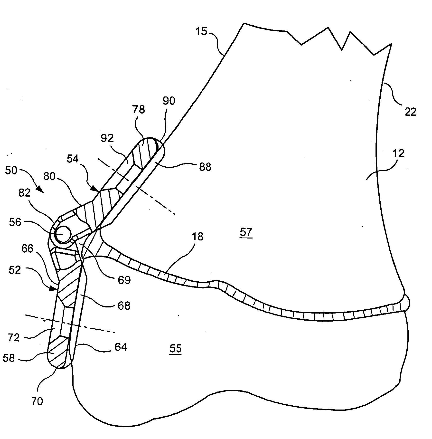
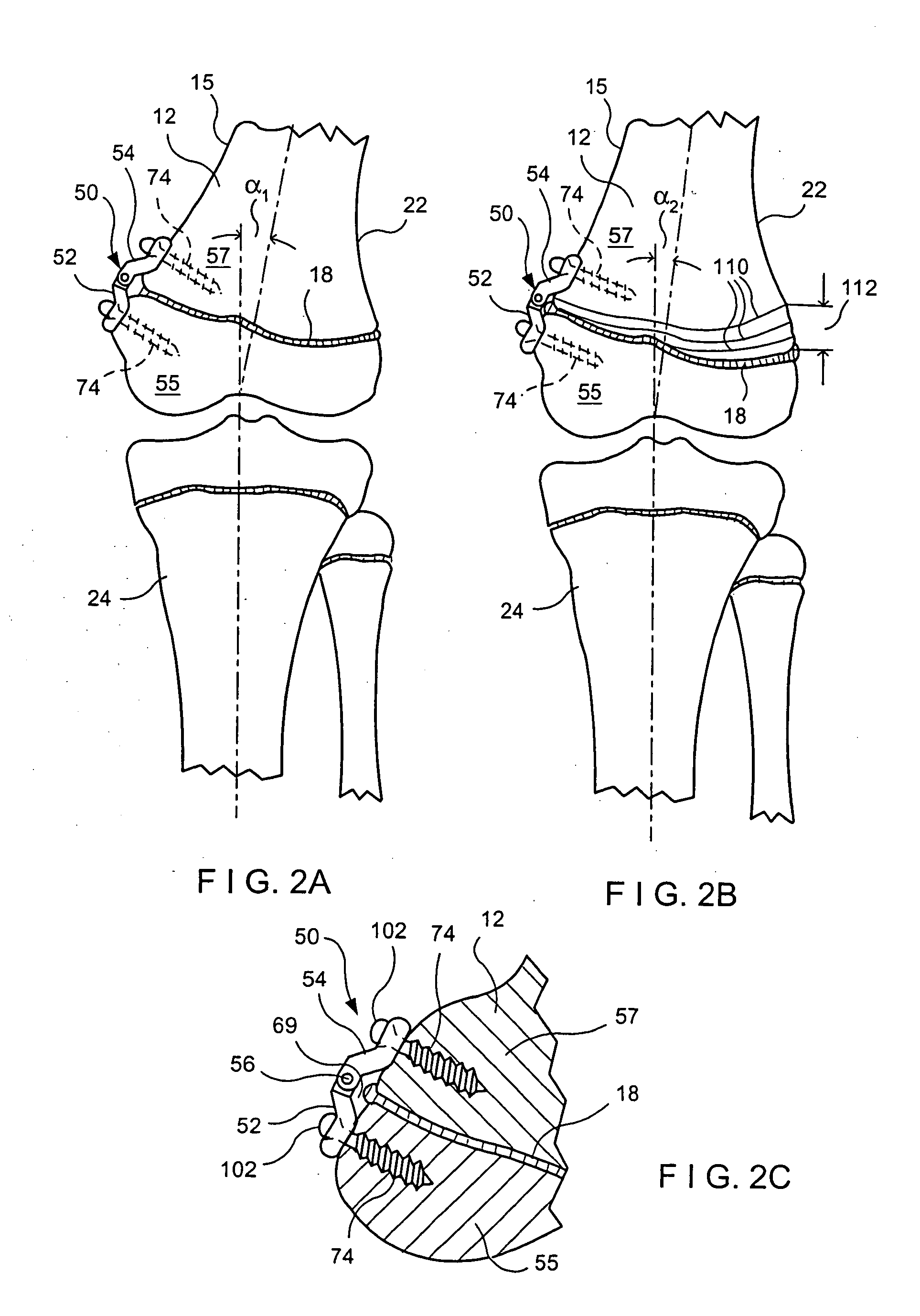
[0032]Referring to the drawings and to FIGS. 2A-2C in particular, wherein a procedure for correcting a genu valgus condition in accordance with an exemplary embodiment of the present invention is illustrated. The procedure includes installing a unique orthopedic device 50 onto the lateral side 15 of the distal femur 12 about the distal femur physis or growth plate 18. For a genu varus condition, the orthopedic device 50 would alternatively be mounted onto the medial side 22 of the distal femur 12 about the growth plate 18. Other locations that may be suitable for installing the orthopedic device 50 may include, without limitation, the growth plate region of proximal tibia, distal tibia, proximal femur, as well as locations on the humerous, ulna and / or radius and spinal formation.

[0033]With further reference to FIGS. 4-10, the orthopedic device 50 includes a first substantially rigid hinge plate 52 pivotally connected to a second substantially rigid hinge plate 54 by means of a hinge...


PUM


Abstract

An orthopedic device and method for correcting angular deformation of a bone structure having a growth plate. The device includes first and second hinge members connected together at a hinge joint. The device is adapted for mounting the orthopedic device to the bone structure with the pivot joint positioned over the growth plate. Alignment of the pivot joint with the growth plate promotes asymmetric growth of the growth plate to thereby correct the angular deformation.

Description

BACKGROUND OF THE INVENTION[0001]This invention relates to correcting angular bone deformities, and more particularly to an orthopedic device and method for correcting angular deformities of the lower extremities, such as genu varus and genu valgus conditions.[0002]Angular bone deformities of the lower extremities are typically characterized by abnormal angulations of the lower leg in relation to the thigh. For example, genu varum is characterized by an abnormal outward bowing of the leg resulting in bowlegs, while genu valgum is characterized by an inward bowing of the leg and is commonly referred to as knock-knees. Under normal conditions, the femur and tibia meet at a tibial-femoral angle of approximately 5-12 degrees of valgus. A greater angle results in a genu valgus condition while a lesser angle results in a genu varum condition. Either of these conditions in one or both legs may result in improper load distribution on the knee joint, causing swelling, knee pain, loss of stab...

Claims


Application Information

Patent Timeline
Patent Type & Authority Applications(United States)
IPC IPC(8): A61B17/80A61B17/88
CPCA61B17/8004A61B17/80A61B17/8061
Inventor GREEN, DANIEL W.MOLINO, JOSEPH L.
Owner PEGA MEDICAL
Learn More