
Optical film

a technology of optical film and film body, applied in the field of optical film, can solve the problems of low production yield, high cost, and inability of structures to reduce mura phenomena, and achieve the effect of reducing optical interferen

Inactive Publication Date: 2009-12-31
ETERNAL MATERIALS CO LTD
View PDF13 Cites 16 Cited by
  • Summary
  • Abstract
  • Description
  • Claims
  • Application Information

AI Technical Summary

Benefits of technology

[0011]The present invention provides an optical film which can reduce optical interference and eliminate the above disadvantages.

Problems solved by technology

Due to the fixed width and regular arrangement of the strip-shaped structures of the brightness enhancing film disclosed in the prior art, optical interference caused by the light rays refracted or reflected by other films of the displays or by the brightness enhancing film itself could be generated, thereby resulting in moiré or mura in appearance.
Such structures cannot reduce mura phenomena.
Since it is difficult to simultaneously emboss two peaks, the production yield is low and the cost is high.
However, this approach increases the cost and complexity of the backlight module structure.

Method used


Image

  • Optical film
  • Optical film
  • Optical film

Examples


Embodiment Construction

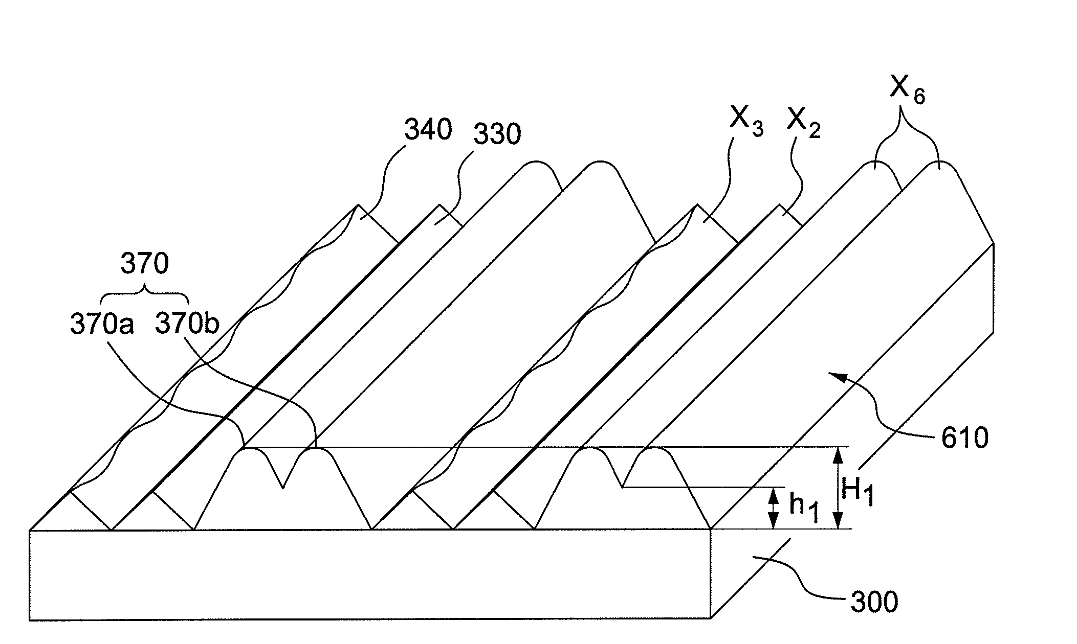
[0017]The term “multi-peaked columnar structure” used herein represents a combined structure composed of at least two columnar structures overlapping each other, and the valley line between any two adjacent columnar structures has a height of 30% to 95% of the height of the lower one of the adjacent columnar structures.

[0018]The term “single-peaked prismatic columnar structure” used herein represents a structure composed of a single prismatic columnar structure with one single peak.

[0019]The term “valley line” used herein represents the line which is formed by the adjacent side surfaces of two adjacent columnar structures.

[0020]The term “height of a columnar structure” used herein represents the perpendicular distance from the peak to the bottom of a columnar structure.

[0021]The term “height of a valley line” used herein represents the perpendicular distance from a valley line to the bottom of the adjacent columnar structures.

[0022]The term “width of a columnar structure” used herei...


PUM

PropertyMeasurementUnit
apex anglesaaaaaaaaaa
heightsaaaaaaaaaa

Abstract

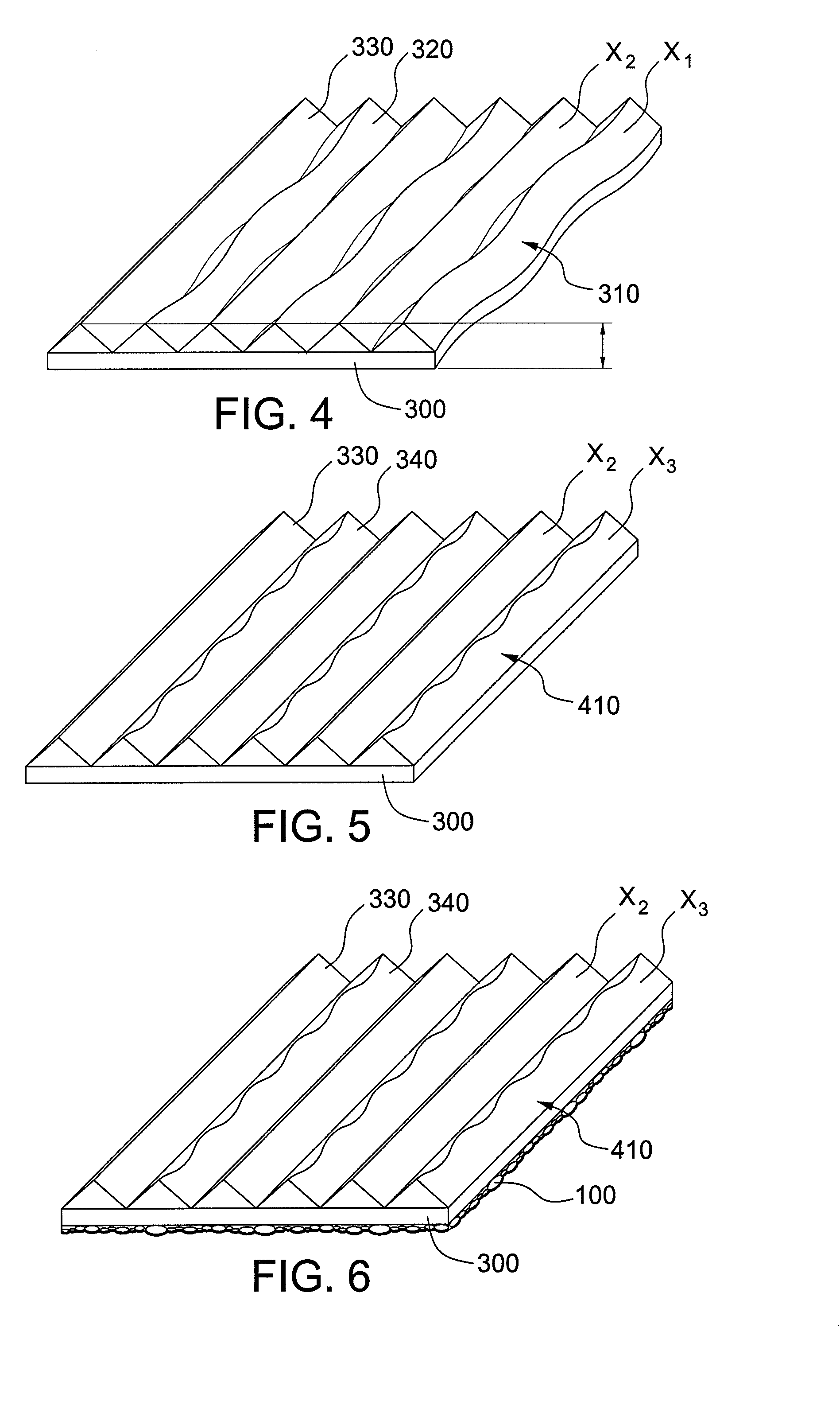
The present invention pertains to an optical film comprising a substrate and a microstructured layer on a surface of the substrate, wherein the microstructured layer comprises a plurality of columnar structures and the columnar structures comprise at least two members selected from the group consisting of a linear columnar structure with its height varying along the length direction, a linear columnar structure without its height varying along the length direction, a serpentine columnar structure with its height varying along the length direction, and a serpentine columnar structure without its height varying along the length direction.The optical film of the present invention enhances the brightness and efficiently reduces optical interference.

Description

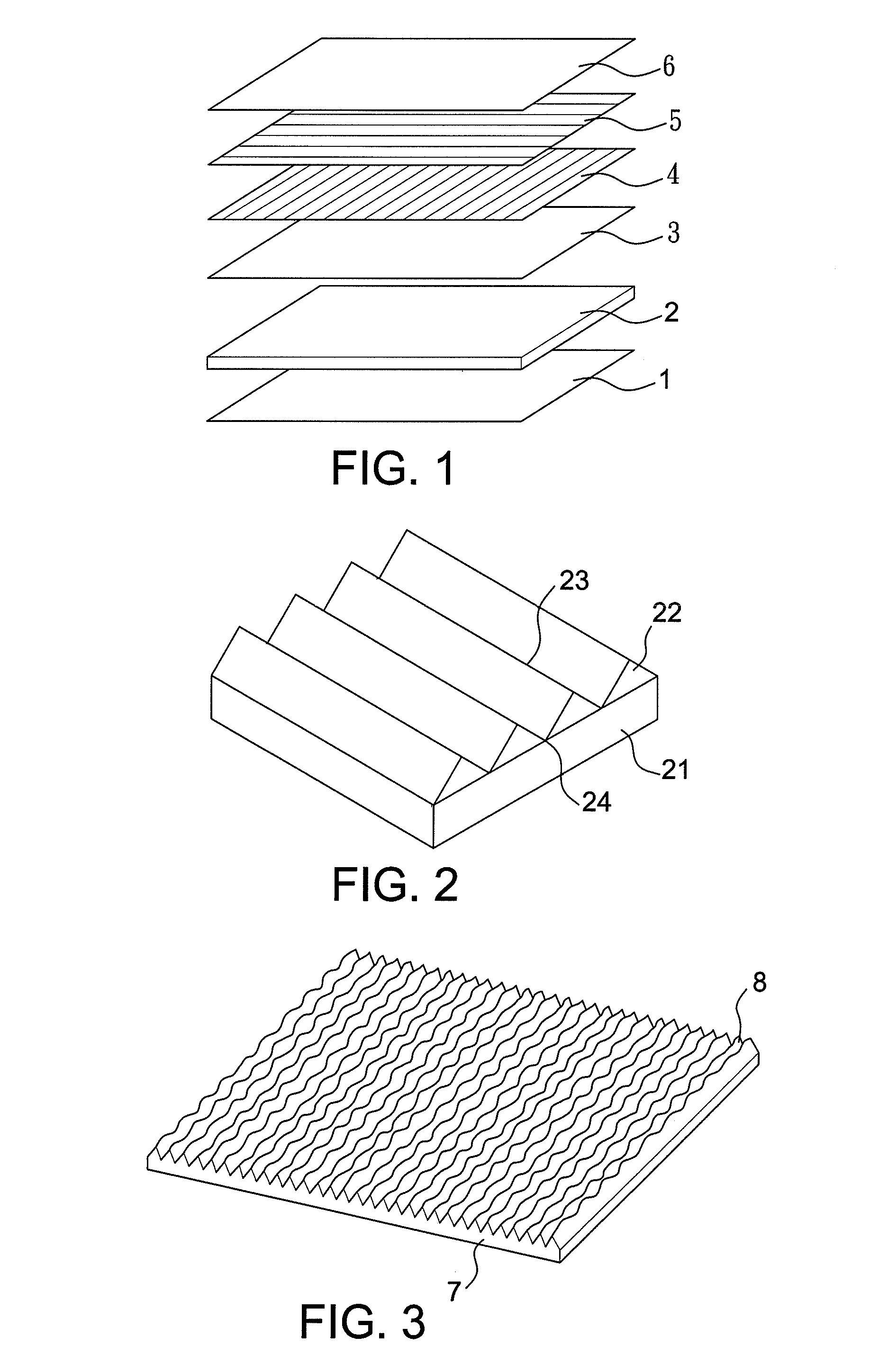
BACKGROUND OF THE INVENTION[0001]1. Field of the Invention[0002]The present invention relates to an optical film, in particular, a brightness enhancing film applicable to liquid crystal displays (LCDs).[0003]2. Description of the Prior Art[0004]It is known that liquid crystal display (LCD) panels cannot emit light, and thus, backlight modules serving as brightness source become important for liquid crystal displays (LCDs) and are crucial for enhancing the brightness of the displays. Currently, various optical films are used in backlight modules to enhance the brightness of LCD panels and to maximize the efficiency of the light sources without altering any elemental design or consuming additional energy. Such an approach has become the most economical and convenient solution.[0005]FIG. 1 is a schematic illustration of the various optical films in a backlight module. As shown in FIG. 1, a typical backlight module comprises a reflective film (1) below a lightguide (2) and other films i...

Claims


Application Information

Patent Timeline
Patent Type & Authority Applications(United States)
IPC IPC(8): B32B3/30
CPCG02B5/02Y10T428/2457G02B5/045G02B5/04G02F1/1335
Inventor WU, TING-YUANGSHIH, YI-CHUNG
Owner ETERNAL MATERIALS CO LTD
Learn More