Variable-power optical system and imaging apparatus
a technology of applied in the field of variable-power optical system and imaging apparatus, can solve problems such as difficulty in achieving optical performance capable, and achieve the effects of wide angle of view, small size, and large aperture ratio
- Summary
- Abstract
- Description
- Claims
- Application Information
AI Technical Summary
Benefits of technology
Problems solved by technology
Method used
Image
Examples
example 1
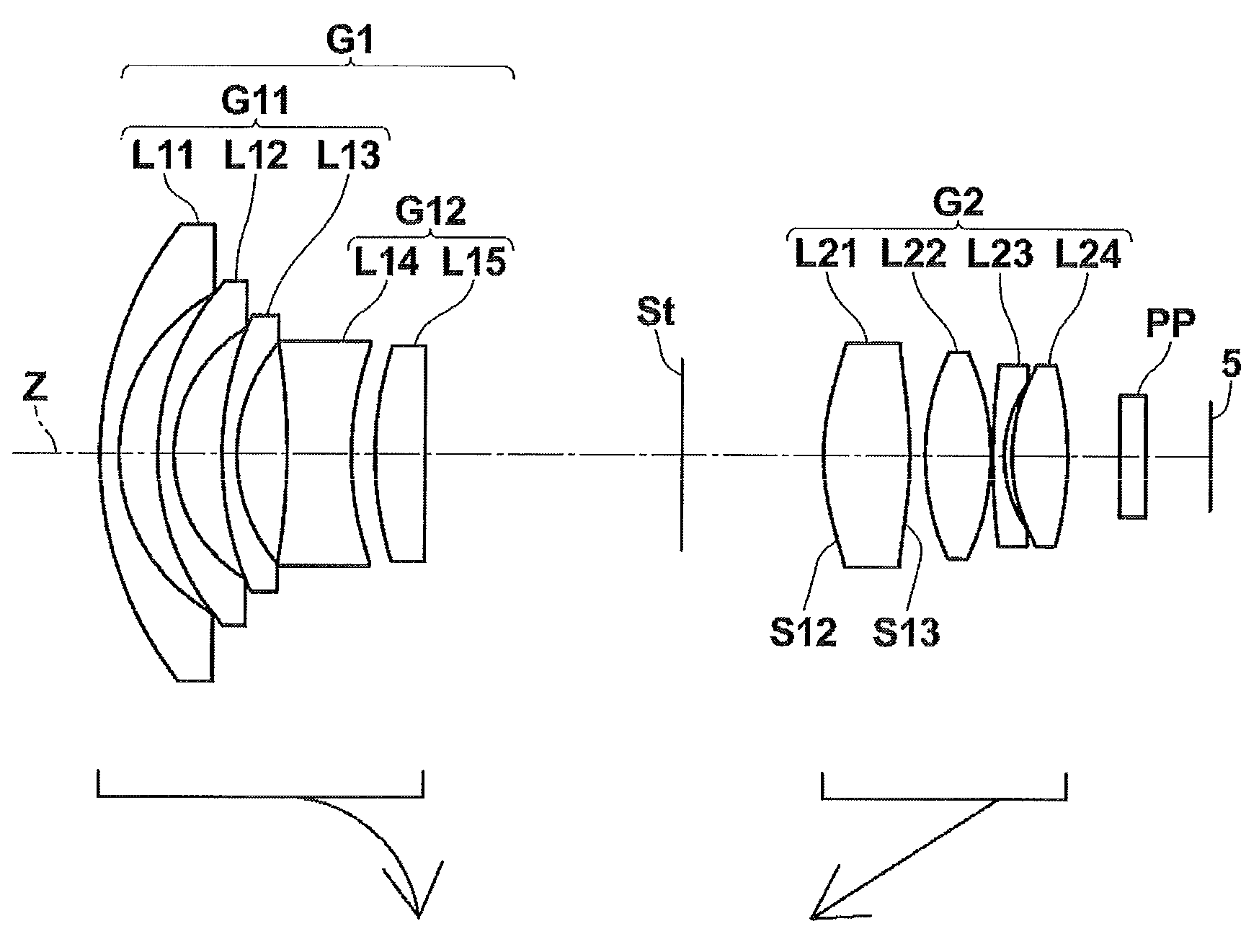
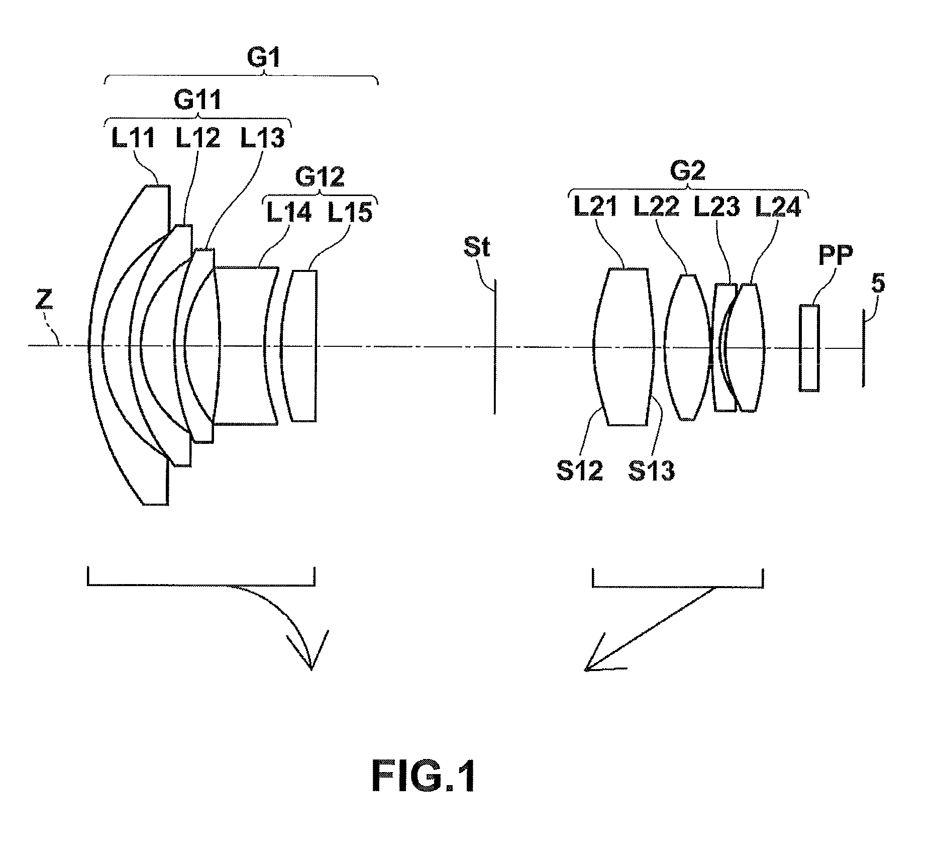
[0074]The cross-sectional view of lenses according to Example 1 is shown in FIG. 1. Specifically, a first lens group G1 of a variable-power optical system according to Example 1 includes meniscus-shaped negative lenses L11, L12, and L13 having convex surfaces facing the object side, a biconcave negative lens L14, and a plano-convex positive lens L15 having a convex surface facing the object side arranged in this order from the object side. The second lens group G2 includes a positive lens L21 having a biconvex shape in the vicinity of the optical axis, a biconvex positive lens L22, a meniscus-shaped negative lens L23 having a convex surface facing the object side, and a biconvex positive lens L24 arranged in this order from the object side. In the variable-power optical system according to Example 1, an object-side surface S12 and an image-side surface S13 of the lens L21 are aspheric surfaces. The position of the aperture stop St is fixed, but the diameter thereof is variable when ...
example 2
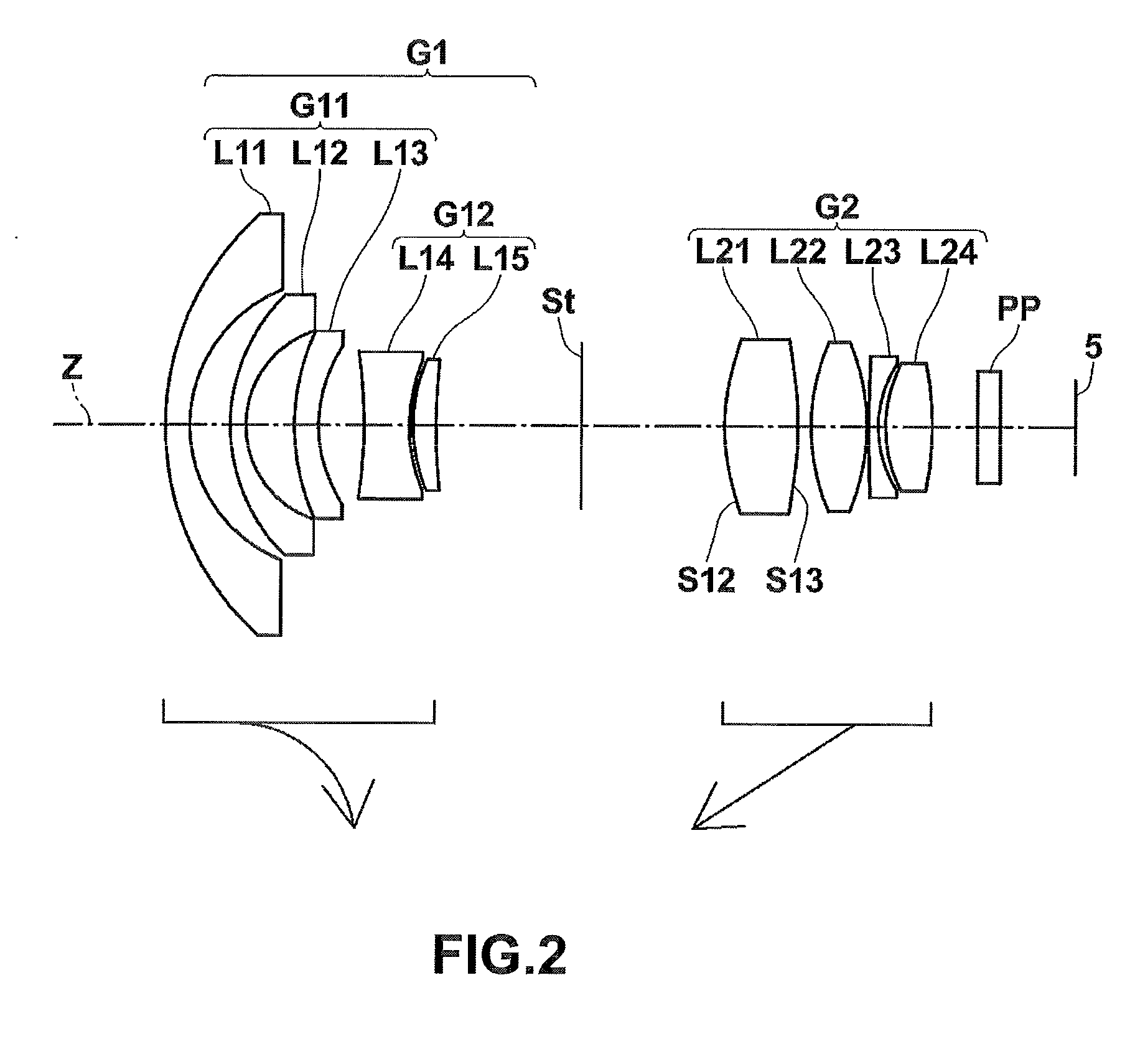
[0081]FIG. 2 is a cross-sectional view illustrating lenses according to Example 2. The basic lens structure of a variable-power optical system according to Example 2 is similar to that according to Example 1 except that a meniscus-shaped positive lens L15 having a convex surface facing the object side is used in Example 2 instead of the plano-convex lens L15 according to Example 1. In addition, in the variable-power optical system according to Example 2, an object-side surface S12 and an image-side surface of a lens L21 are aspheric surfaces.
[0082]Lens data of the variable-power optical system according to Example 2 is shown in Table 4, aspheric data thereof is shown in Table 5, and various data thereof is shown in Table 6.
TABLE 4Example 2Lens dataSiRiDiNdjνdj 118.85441.671.8830040.8 29.68982.70 312.07471.071.8830040.8 46.61673.26 514.74791.641.8160046.6 69.56463.03 7−31.77503.051.7995242.2 811.31380.24 910.82961.551.9228618.91039.8198Variablespacing D111 (aperture stop)—Variablespa...
example 3
[0083]FIG. 3 is a cross-sectional view illustrating lenses according to Example 3. The basic lens structure of a variable-power optical system according to Example 3 is the same as that according to Example 2. In addition, in the variable-power optical system according to Example 3, an object-side surface S12 and an image-side surface S13 of a lens L21 are aspheric surfaces.
[0084]Lens data of the variable-power optical system according to Example 3 is shown in Table 7, aspheric data thereof is shown in Table 8, and various data thereof is shown in Table 9.
TABLE 7Example 3Lens dataSiRiDiNdjνdj 121.89431.261.8348142.7 211.73352.92 314.64511.101.8830040.8 410.17642.84 516.46760.951.8830040.8 610.74454.17 7−35.78103.101.8040046.6 816.10171.81 921.68363.101.9228618.910604.6536Variablespacing D111 (aperture stop)—Variablespacing D212*10.79944.241.4970081.613*−93.96860.781410.00282.861.7291654.715−32.29760.321636.88480.822.0006925.5176.39900.671814.41201.581.6180063.419−18.2038Variablespac...
PUM
 Abstract
Description
Claims
Application Information
 - R&D
- Intellectual Property
- Life Sciences
- Materials
- Tech Scout
- Unparalleled Data Quality
- Higher Quality Content
- 60% Fewer Hallucinations
Browse by: Latest US Patents, China's latest patents, Technical Efficacy Thesaurus, Application Domain, Technology Topic, Popular Technical Reports.
© 2025 PatSnap. All rights reserved.Legal|Privacy policy|Modern Slavery Act Transparency Statement|Sitemap|About US| Contact US: help@patsnap.com


