
Vehicle-installed obstacle detecting system and method

a detection system and obstacle technology, applied in the direction of television systems, pedestrian/occupant safety arrangements, instruments, etc., can solve the problems of high possibility of collision, delay in detection of obstacles having a high possibility of colliding with vehicles after a short time,

Active Publication Date: 2009-12-31
TOYOTA JIDOSHA KK
View PDF1 Cites 7 Cited by
  • Summary
  • Abstract
  • Description
  • Claims
  • Application Information

AI Technical Summary

Benefits of technology

[0006]It is an object of the invention to provide a vehicle-installed obstacle detecting system that is able to detect an obstacle having a high possibility of colliding with the vehicle, within a shorter period of time.

Problems solved by technology

In a system of the related art, a captured image is scanned from the upper side (remote from the vehicle) toward the lower side (close to the vehicle) on the image, and therefore, detection of an obstacle having a high possibility of colliding with the vehicle after a short time may be delayed.
Therefore, the system is able to detect an obstacle located close to the vehicle and having a high possibility of colliding with the vehicle, within a short period of time.

Method used


Image

  • Vehicle-installed obstacle detecting system and method
  • Vehicle-installed obstacle detecting system and method
  • Vehicle-installed obstacle detecting system and method

Examples


Embodiment Construction

[0029]Vehicle-installed obstacle detecting systems according to some embodiments of the invention will be described with reference to the accompanying drawings.

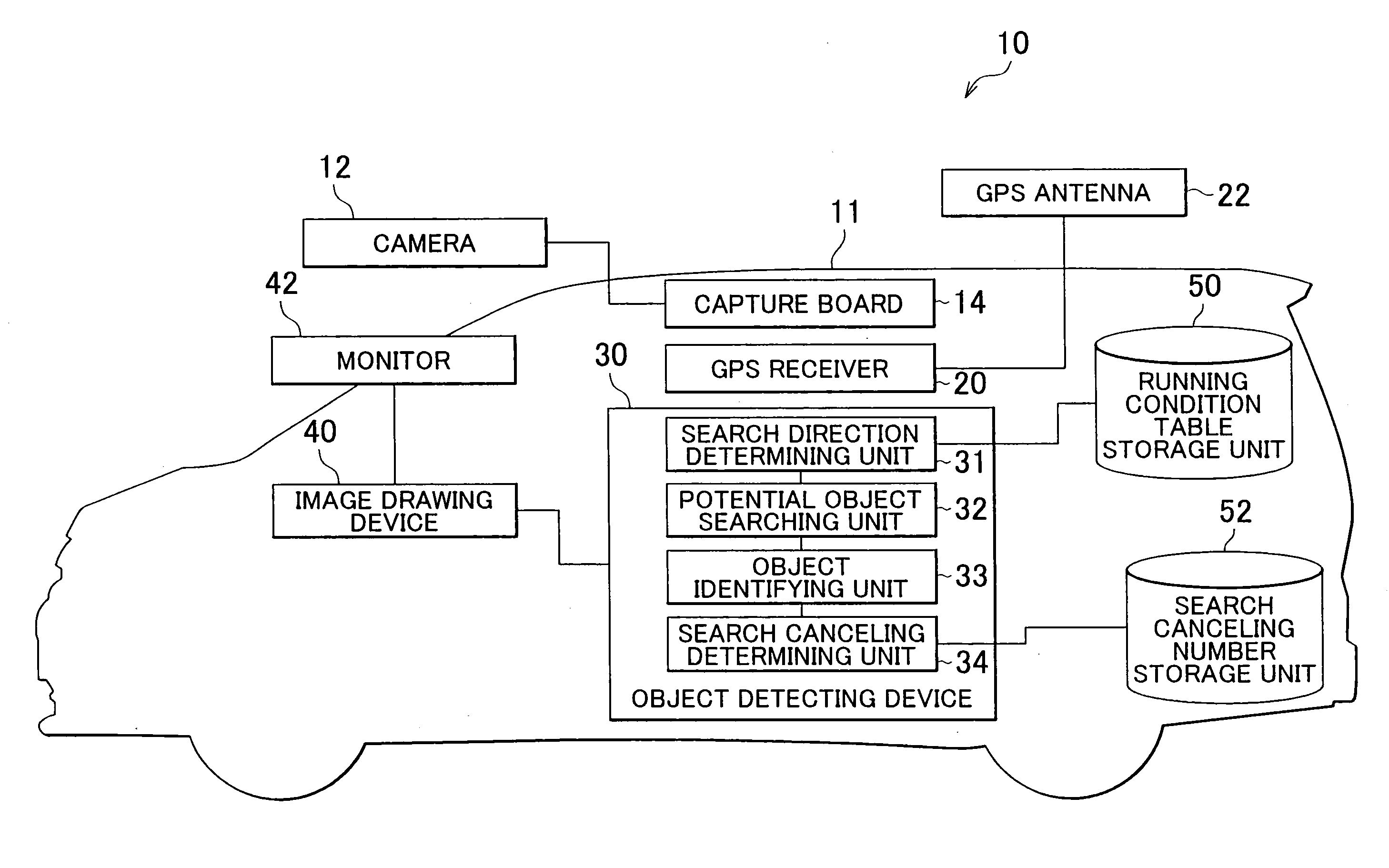
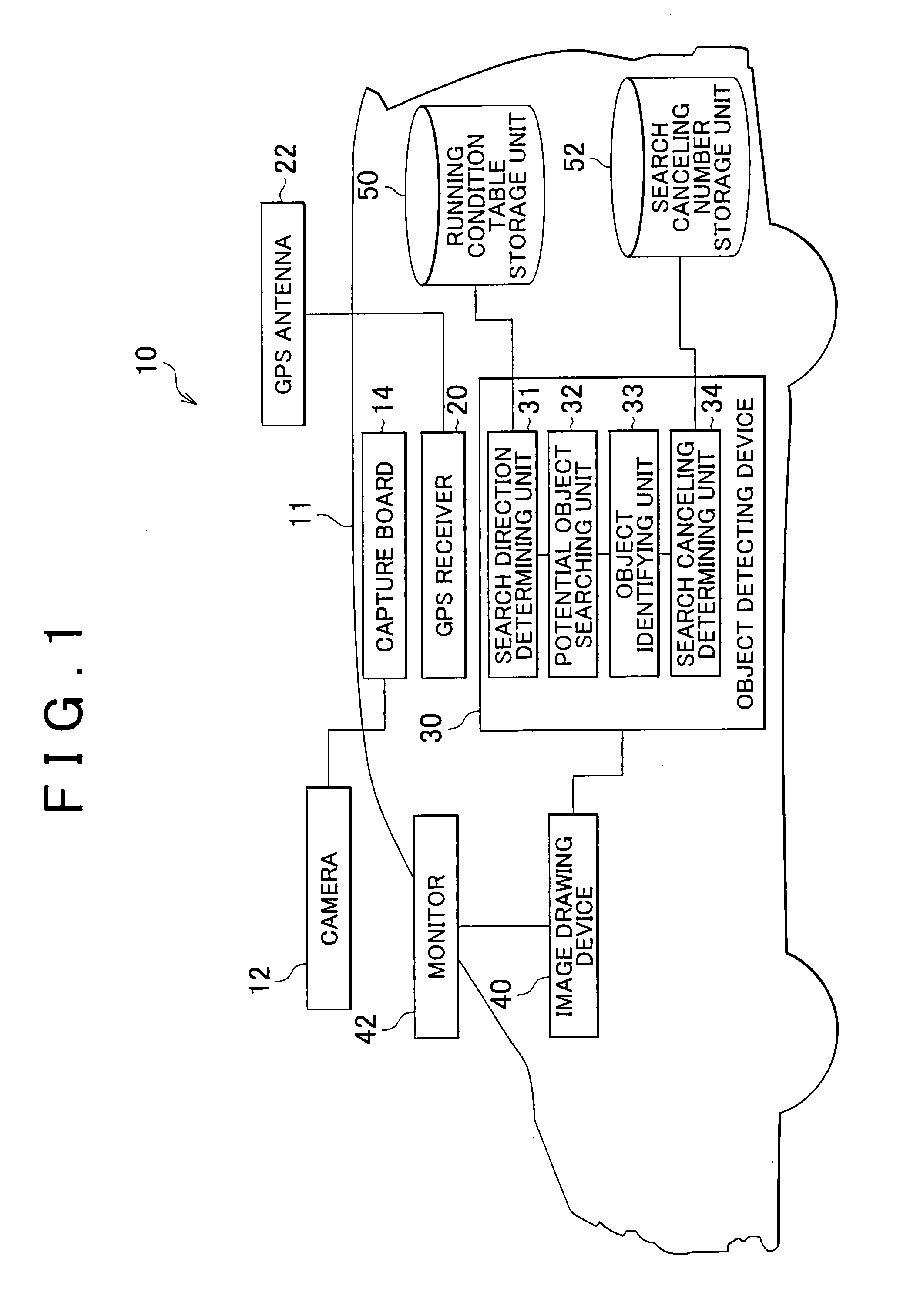
[0030]FIG. 1 is a block diagram showing the construction of a vehicle-installed obstacle detecting system according to a first embodiment of the invention. The vehicle-installed obstacle detecting system of this embodiment is arranged to detect obstacles, such as pedestrians, which may collide with the vehicle during running of the vehicle, and draw the attention of the vehicle driver to the obstacles. As shown in FIG. 1, the vehicle-installed obstacle detecting system 10 of this embodiment includes a camera (image capturing means) 12, capture board 14, GPS receiver (road information acquiring means) 20, GPS antenna 22, object detecting device (detecting means) 30, image drawing device 40, monitor 42, running condition table storage unit 50, and a search canceling number storage unit 52 for storing the number of objects based...


PUM


Abstract

An object detecting device scans an image captured by a camera from one side close to the vehicle to the other side remote from the vehicle for detection of an obstacle through pattern matching, so that an obstacle that is close to the vehicle and is likely to collide with the vehicle can be detected in a short time. Thus, the driver is informed of the presence of an obstacle having a high risk of collision, earlier than other obstacles located ahead of the vehicle.

Description

BACKGROUND OF THE INVENTION[0001]1. Field of the Invention[0002]The invention relates to vehicle-installed obstacle detecting system and method, and more particularly to vehicle-installed obstacle detecting system and method for detecting obstacles in surroundings of the vehicle through pattern matching.[0003]2. Description of the Related Art[0004]Vehicle-installed obstacle detecting systems have been proposed which are arranged to detect pedestrians through pattern matching. For example, a moving object detecting system as disclosed in Japanese Patent Application Publication No. 2002-99997 (JP-A-2002-99997) specifies a road region based on image information received from a CCD camera, and combines the road region information with infrared image information received from an infrared camera so as to search for and specify a pedestrian or pedestrians within the road region through template matching. Thus, the moving object detecting system detects a pedestrian on a screen within the r...

Claims


Application Information

Patent Timeline
Patent Type & Authority Applications(United States)
IPC IPC(8): B60Q1/00H04N5/00B60R1/00B60R21/00G08G1/16H04N7/18
CPCG08G1/166G08G1/16
Inventor OZAKI, OSAMU
Owner TOYOTA JIDOSHA KK
Learn More