Systems and methods for ethernet extension and demarcation

Active Publication Date: 2009-12-24
LUMENTUM OPERATIONS LLC
View PDF12 Cites 74 Cited by
  • Summary
  • Abstract
  • Description
  • Claims
  • Application Information

AI Technical Summary

Benefits of technology

[0013]In various exemplary embodiments, the present invention provides Ethernet extension and demarcation functionality through a pluggable transceiver in a customer device. The pluggable transceiver is configured to frame an Ethernet client signal and to provide OAM&P functionality, such as with G.709 framing. The pluggable transceiver operates within existing multi-source agreement (MSA) specifications. Accordingly, the pluggable transceiver can operate in any customer device compliant to the MSA specifications. Additionally, the framing and OAM&P functionality are transparent to the customer device, but instead utilized by a service provider for demarcation functionality, eliminating the requirements for external demarcation equipment and for external transponders.

Problems solved by technology

Advantageously, this enables interoperability among equipment vendors of pluggable transceivers, i.e. any MSA-compatible pluggable transceiver can be used in any host system designed to the MSA specification; however, these tightly defined characteristics limit the performance of pluggable transceivers since the MSA specifications were designed to maximize density and minimize cost, and not to provide advanced optical performance.
The MSA specifications have not addressed performance enhancements to enable pluggable transceivers to extend reach beyond 80 km and to provide carrier-grade optical management and performance.
As such, the use of pluggable transceivers to date has been limited to intra-office connections, short reach enterprise and metro networks (less than 80 km), and connection to an optical transponder capable of extended reach typically beyond 80 km.

Method used


Image

  • Systems and methods for ethernet extension and demarcation
  • Systems and methods for ethernet extension and demarcation
  • Systems and methods for ethernet extension and demarcation

Examples


Embodiment Construction

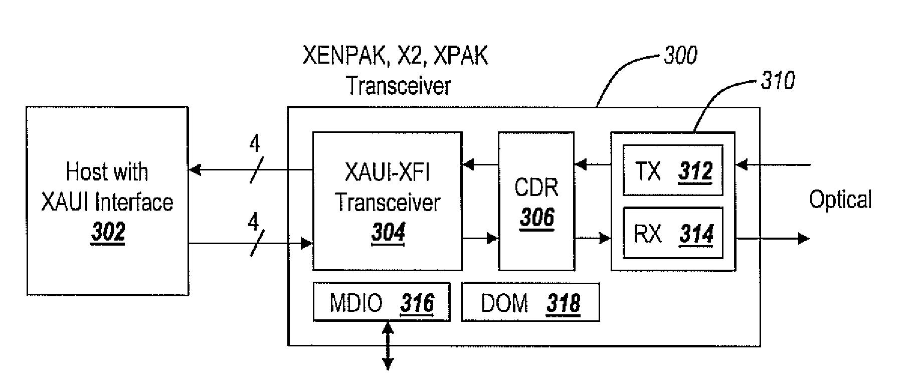
[0043]In various exemplary embodiments, the present invention provides Ethernet extension and demarcation functionality through a pluggable transceiver in a customer or remote device. The pluggable transceiver is configured to frame an Ethernet client signal and to provide OAM&P functionality, such as with G.709 framing. The pluggable transceiver operates within existing multi-source agreement (MSA) specifications. Accordingly, the pluggable transceiver can operate in any customer device compliant to the MSA specifications. Additionally, the framing and OAM&P functionality can be transparent to the customer or remote device, and can be instead utilized by a service provider for demarcation functionality, eliminating the requirements for external demarcation equipment and for external transponders.

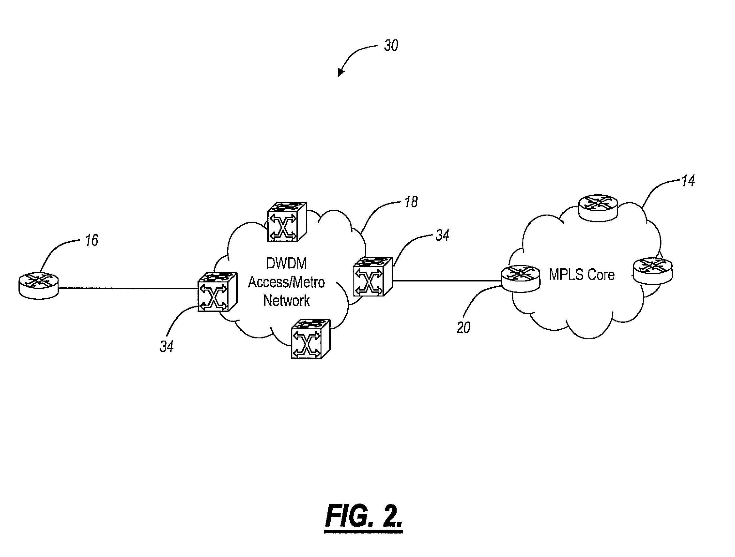
[0044]Referring to FIG. 2, an Ethernet extension application is illustrated in a network 30 utilizing pluggable optical transceivers for demarcation according to an exemplary embodiment of ...


PUM


Abstract

The present invention provides Ethernet extension and demarcation functionality through a Multi-Source Agreement (MSA) pluggable transceiver in a customer or remote device. The pluggable transceiver is configured to frame an Ethernet client signal and to provide OAM&P functionality, such as with G.709 framing. The pluggable transceiver operates within existing multi-source agreement (MSA) specifications. Accordingly, the pluggable transceiver can operate in any customer device compliant to the MSA specifications. Additionally, the framing and OAM&P functionality are transparent to the customer device, but instead utilized by a service provider for demarcation functionality, eliminating the requirements for external demarcation equipment and for external transponders.

Description

CROSS-REFERENCE TO RELATED APPLICATION(S)[0001]The present non-provisional patent application claims priority to U.S. Provisional Patent Application Ser. No. 61 / 029,821, filed Feb. 19, 2008, and entitled “SYSTEMS AND METHODS FOR ETHERNET EXTENSION AND DEMARCATION,” which is incorporated in full by reference herein. Further, the present non-provisional patent application is a continuation-in-part of commonly assigned U.S. patent application Ser. No. 11 / 581,201, filed on Oct. 13, 2006, and entitled “SYSTEMS AND METHODS FOR THE INTEGRATION OF FRAMING, OAM&P, AND FORWARD ERROR CORRECTION IN PLUGGABLE OPTICAL TRANSCEIVER DEVICES,” which is incorporated in full by reference herein.FIELD OF THE INVENTION[0002]The present invention relates generally to optical and data networking, and more specifically to systems and methods for Ethernet extension and demarcation utilizing pluggable transceiver devices configured to utilize Optical Transport Network (OTN) framing to provide operations, admi...

Claims


Application Information

Patent Timeline
IPC IPC(8): H04B10/08H04B10/00H04J14/00
CPCH04L41/50H04L41/08H04L41/00H04J3/1652
Inventor HOTCHKISS, ADAM R.EL-AHMADI, SIRAJ NOUREL-AHMADI, SALAMWILCOX, REGINALD
Owner LUMENTUM OPERATIONS LLC
Why Eureka
Try Eureka