Deployment of telescoping aircraft structures by drogue parachute riser tension

Inactive Publication Date: 2009-12-24
AURORA FLIGHT SCI CORP
View PDF20 Cites 10 Cited by
  • Summary
  • Abstract
  • Description
  • Claims
  • Application Information

AI Technical Summary

Benefits of technology

[0007]It is therefore a general aspect of the invention to provide a telescoping structure deployment system that will obviate or minimize problems of the type previously described.
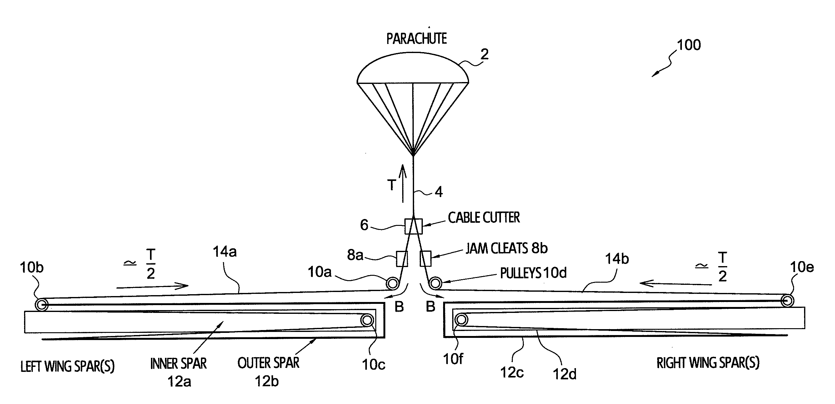
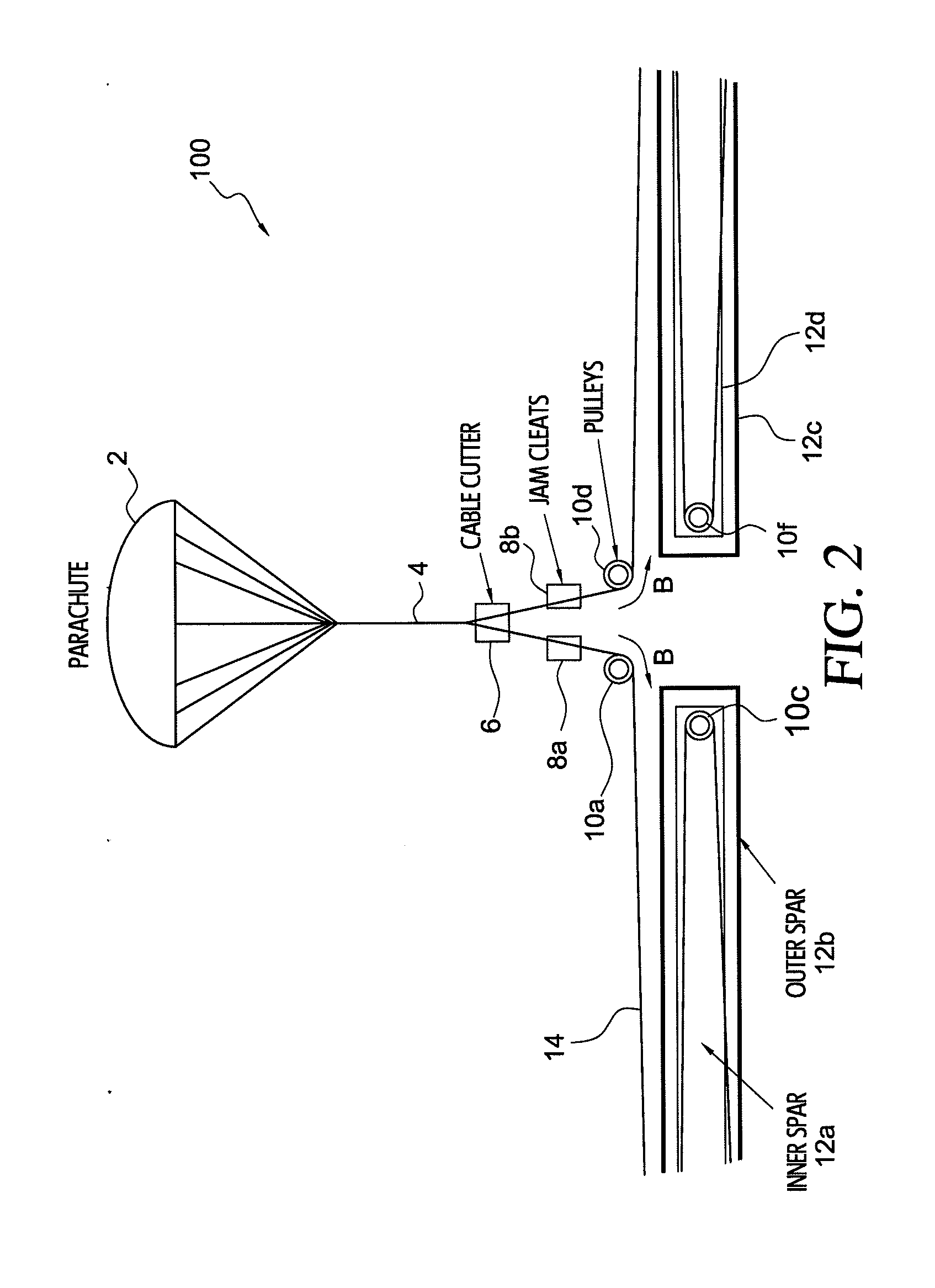
[0008]It is now becoming common to launch an unmanned aircraft in a folded configuration. The folding allows a large aircraft to be stowed and carried or launched in some sort of a small volume container. In many cases, the aircraft is launched by a small booster rocket, such as a typical cruise missile. In this case the aircraft is unfolded immediately after exiting the container, while still at low airspeed, and thus with low air loads. However, in other cases, the aircraft can be launched from a larger aircraft flying at high speed, or it can be launched to a high altitude by a large booster rocket, or it can even be launched to another planet. In all of these cases the aircraft must deploy itself at a high airspeed, with high aerodynamic forces. It is often desirable to use some sort of a parachute system to stabilize the aircraft as it unfolds, and sometimes the parachute is also used to retard or even decelerate the aircraft to further minimize the aerodynamic loads on the aircraft. Accordingly, several exemplary embodiments make use of the drag force on the parachute to provide a large amount of work to effectively deploy the aircraft with little or no additional weight penalty. While the exemplary embodiment has particular applicability to telescoping structures, which inherently require very large displacements for deployment, the structural deployment system is also useful for deploying hinged type structures. If the parachute is large enough to decelerate the aircraft, the force available is greater than the weight of the aircraft.

Problems solved by technology

In all of these cases the aircraft must deploy itself at a high airspeed, with high aerodynamic forces.

Method used


Image

  • Deployment of telescoping aircraft structures by drogue parachute riser tension
  • Deployment of telescoping aircraft structures by drogue parachute riser tension
  • Deployment of telescoping aircraft structures by drogue parachute riser tension

Examples


Embodiment Construction

[0047]The various features of the preferred embodiments will now be described with reference to the drawing figures, in which like parts are identified with the same reference characters. The following description of the presently contemplated best mode of practicing the invention is not to be taken in a limiting sense, but is provided merely for the purpose of describing the general principles of the invention.

[0048]According to an exemplary embodiment, a drogue parachute telescoping aircraft structure deployment pulley and cable system (parachute deployment system) 100 uses a series of cables and pulleys to deploy telescoping / foldable aircraft structures (hereinafter referred to as “deployable structures”) for light-weight aircraft 50. According to an exemplary embodiment, light-weight aircraft 50 is defined to weigh less than about 5,000 lbs or less. According to a preferred embodiment, the telescoping structure is a wing spar structure. According to further exemplary embodiments...


PUM


Abstract

A system for deploying a deployable structure in an aircraft, comprising a drogue parachute, at least one deployable structure, a riser line attached to the drogue parachute and the at least one deployable structure, wherein when the drogue parachute is deployed, a tension is applied to the riser line, and a parachute deployment system, wherein the parachute deployment system is configured to utilize the applied tension to deploy the at least one deployable structure.

Description

PRIORITY[0001]The present application claims priority under 35 U.S.C. § 119(e) to U.S. Provisional Patent Application No. 60 / 943,830, filed Jun. 13, 2007, the entire contents of which are herein expressly incorporated by reference.BACKGROUND OF THE INVENTION[0002]1. Field of the Invention[0003]The invention is related to light-weight aircraft. More particularly, the invention is related to a system and method for extending telescoping aircraft structures without use of existing or auxiliary engines.[0004]2. Background Art[0005]For many types of foldable aircraft, telescoping structures have several advantages. They are simple, light, and inherently occupy a very small amount of stowed volume. However, deployment of such structures typically requires very large displacements of an actuating device. In conventional systems, either inflatable bladders with a compressed gas supply, or a cable and winch system would be used. In addition, the power to operate such devices might have to be...

Claims


Application Information

Patent Timeline
IPC IPC(8): B64C1/00B64C3/56B64C25/10
CPCB64C3/56B64C25/20Y10T24/39B64C2201/102B64D17/80B64C39/024B64U30/12B64U70/20B64U10/25
Inventor CLANCY, TOMPARKS, ROBERT
Owner AURORA FLIGHT SCI CORP
Why Eureka
Try Eureka