
Hybrid image stabilization for video camera

a technology video camera, which is applied in the field of hybrid image stabilization for video camera, can solve the problems of inability to use electronic stabilization procedures

Active Publication Date: 2009-12-17
THALES SA
View PDF8 Cites 77 Cited by
  • Summary
  • Abstract
  • Description
  • Claims
  • Application Information

AI Technical Summary

Benefits of technology

[0007]The aim of the invention is to be able to use a low-cost image stabilization method operating whatever the content of the image (contrasted or not, structured or not, etc.).
[0013]The advantage of the hybrid motion estimation is thus to allow stabilization of the image sequence (of the image stream) whatever the scene.

Problems solved by technology

“A posteriori” electronic stabilization procedures are not usable in the case of images exhibiting a uniform background structure or a repetitive texture (sky, forest or maritime surface for example).

Method used


Image

  • Hybrid image stabilization for video camera
  • Hybrid image stabilization for video camera
  • Hybrid image stabilization for video camera

Examples


Embodiment Construction

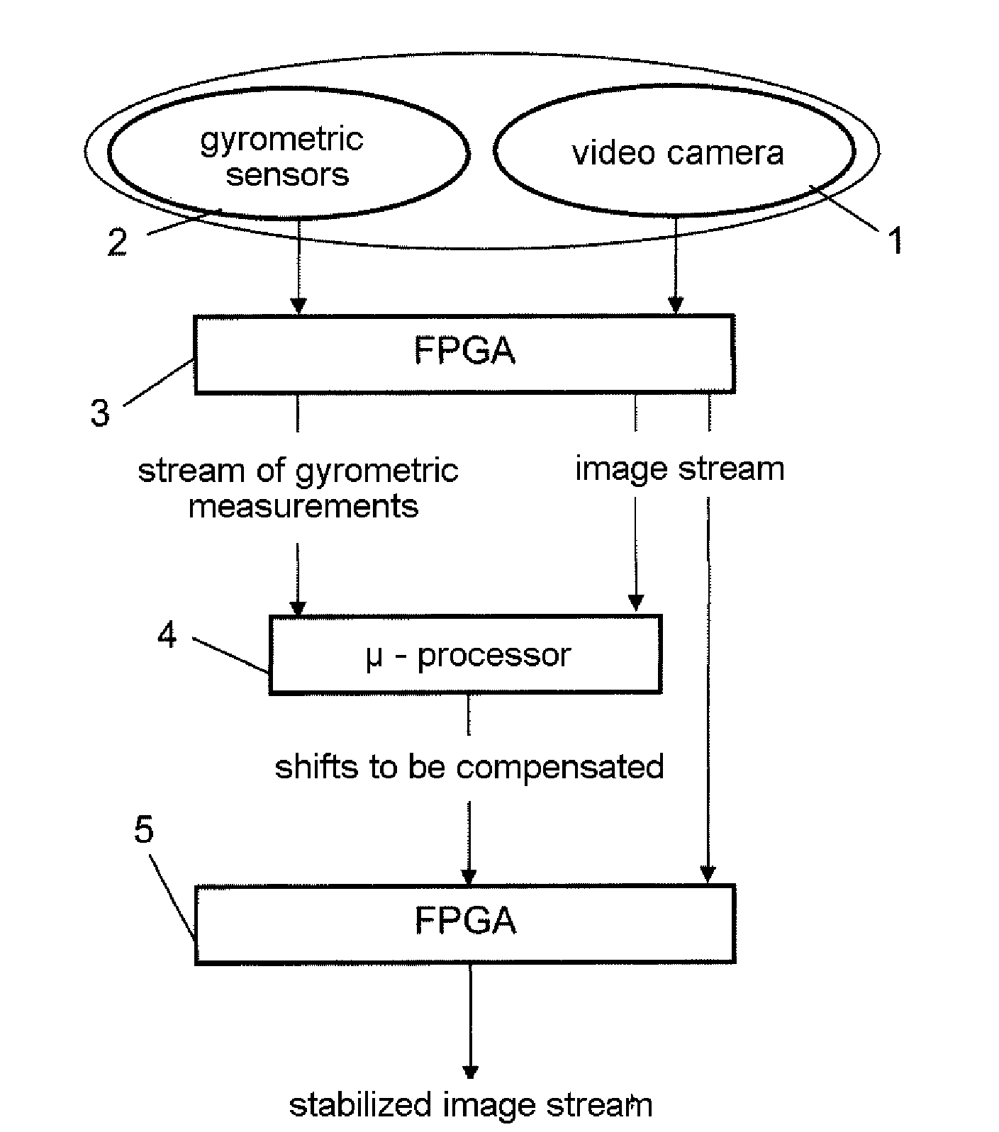
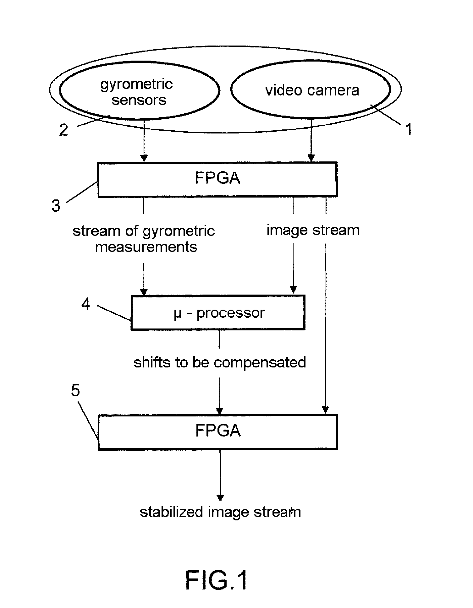
[0035]An exemplary stabilization device according to the invention is represented in FIG. 1.

[0036]It comprises a video camera 1 and two gyrometric sensors 2 secured to the camera. The image of the camera comprising pixels distributed in rows (x axis) and columns (y axis); there is preferably one sensor for the pixel rows and another for the columns. These sensors are typically MEMS (acronym of the expression “Micro Electro Mechanical System”) embodied on silicon. They are linked to an FPGA 3 (acronym of the expression Field Programmable Gate Array). It is recalled that an FPGA is a user-programmable prediffused array of logic gates, used for a particular function. The FPGA delivers an image stream and a stream of gyrometric measurements; these streams are synchronized in such a way that the shift measured by the rate gyros is referred to the corresponding image.

[0037]These information streams are processed by a microprocessor 4. This processing of the streams of images and synchroni...


PUM


Abstract

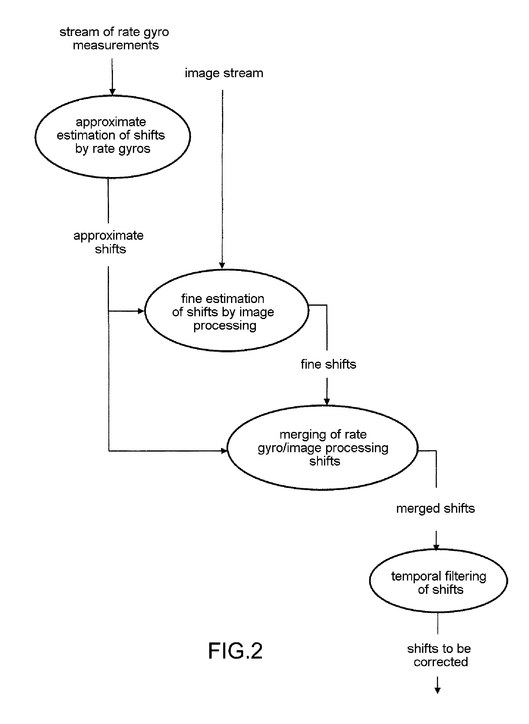
The invention relates to a method of stabilizing the images of a scene, acquired by means of an observation device of an imaging system, comprising the step of digital processing of a stream of successive images. It comprises a step of acquiring gyrometric measurements by means of at least one gyrometric sensor secured to the observation device, of using these gyrometric measurements to determine so-called approximate shifts undergone between successive images, and the image processing step comprising a sub-step of using the approximate shifts and the image stream acquired to determine so-called fine shifts undergone between successive images.

Description

CROSS-REFERENCE TO RELATED APPLICATIONS[0001]The present Application is based on International Application No. PCT / EP2007 / 056294, filed on Jun. 25, 2007, which in turn corresponds to French Application No. 06 05885 filed on Jun. 29, 2006, and priority is hereby claimed under 35 USC § 119 based on these applications. Each of these applications are hereby incorporated by reference in their entirety into the present application.FIELD OF THE INVENTION[0002]The invention relates to the stabilization of an image sequence acquired by an observation device of an imaging system such as a video camera, subject to unintentional movements or vibrations. The observation device typically operates at wavelengths in the visible or infrared region.BACKGROUND OF THE INVENTION[0003]A first solution relates to the video cameras on board a terrestrial, naval or aerial platform which are in general mounted on an orientable mount, for example of the theodolite type, or else in a sighting instrument having...

Claims


Application Information

Patent Timeline
Patent Type & Authority Applications(United States)
IPC IPC(8): H04N5/228
CPCH04N5/23248H04N5/23264H04N5/23258H04N23/68H04N23/6812H04N23/682
Inventor BOURGAIN, STEPHANEBUSTIN, BRUNOFOURNIER, JEROMEPAYOT, ETIENNERANNOU, CHRISTOPHERIOLAND, JACQUES
Owner THALES SA
Learn More