
Center pivot irrigation system diagnostic tool

a technology of irrigation system and diagnostic tool, which is applied in the direction of testing/monitoring control system, program control, instruments, etc., can solve the problems of inability to reliably and accurately diagnose and fix the motor, the process required for diagnosing and fixing the motor can be time-consuming, and the problem of inability to reliably and reliably provide mobile phone service is not easy to solv

Inactive Publication Date: 2009-12-17
L & W INNOVATIONS
View PDF13 Cites 2 Cited by
  • Summary
  • Abstract
  • Description
  • Claims
  • Application Information

AI Technical Summary

Benefits of technology

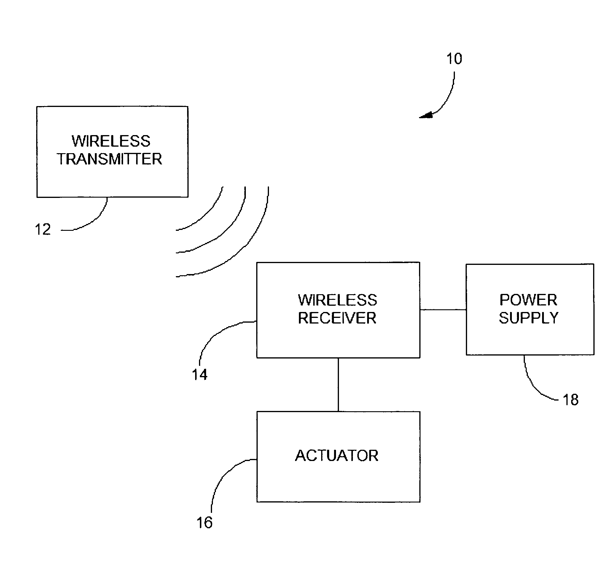
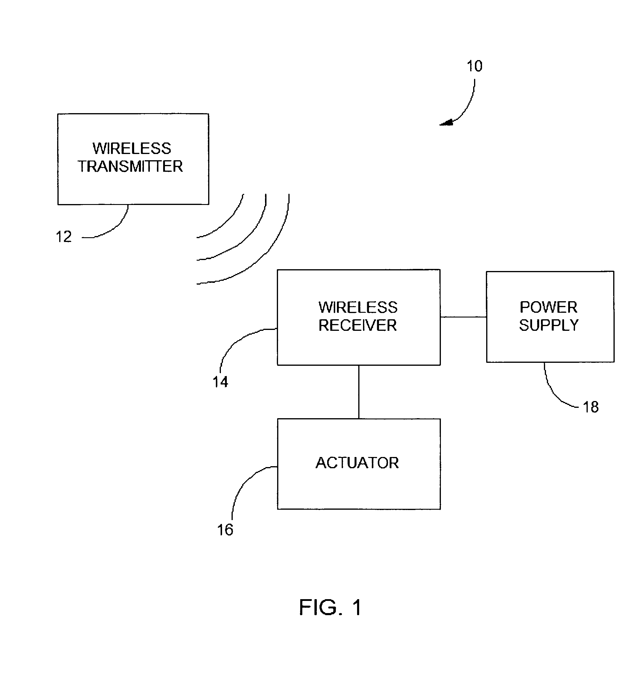
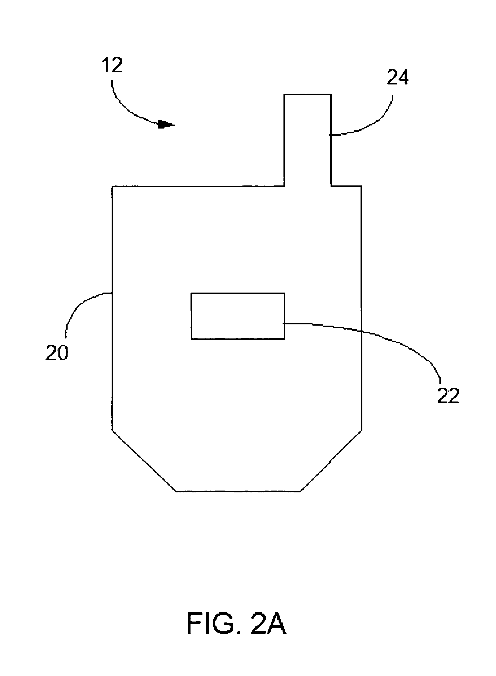
[0006]An embodiment of the invention is a device which serves as a diagnostic tool for an agricultural field irrigation system that has a control panel including at least depressible operating switches for controlling the operation of the system. The diagnostic tool includes a wireless transmitter, a wireless receiver and an actuator. The wireless transmitter is configured to selectively encode and transmit an encoded signal, and the wireless receiver is configured to receive and decode the encoded signal, and provide an output signal to activate the actuator. The actuator is operatively connected to the wireless receiver, and is configured to be removably secured to the control panel. The actuator activates at least one of the system operating switches in response to receipt of the output signal from the receiver.

Problems solved by technology

The center pivot irrigation systems occasionally malfunction.
When this occurs, the process required for diagnosing and fixing the motor can be time consuming, requiring several trips through the field to repair.
However, in some rural farming areas, mobile phone service is unreliable or simply non-existent.
Not only are these panels more costly than a typical control panel, but separate panels must be purchased for each center pivot irrigation system the user wishes to control via a mobile phone.
Additionally, there is sometimes a time delay of up to an hour or more between issuing a command to the control panel via mobile phone and execution of the command by the control panel.

Method used


Image

  • Center pivot irrigation system diagnostic tool
  • Center pivot irrigation system diagnostic tool
  • Center pivot irrigation system diagnostic tool

Examples


Embodiment Construction

[0013]An embodiment of the invention is a device used to start the center pivot irrigation system remotely, and that a safety switch located at one of the mobile towers can be used to stop the irrigation system, once the problem has been diagnosed. It is also contemplated that the device can be used to start and stop the center pivot irrigation system remotely, as well as control the irrigation system's direction of rotation, and cause the system to operate in a safety override mode.

[0014]A preferred embodiment of the diagnostic tool includes a wireless transmitter, a wireless receiver, and an actuator connected to the receiver. The actuator may be removably mounted on a control panel for a center pivot irrigation system, and is used to start and stop the irrigation system from a distance, reducing the traveling distance, and thus the time required of a user when diagnosing a malfunctioning center pivot irrigation system.

[0015]Preferred embodiments of the invention will now be discu...


PUM


Abstract

A diagnostic tool for an agricultural field irrigation system that has a control panel including at least depressible operating switches for controlling the operation of the system includes a wireless transmitter, a wireless receiver and an actuator. The wireless transmitter is configured to selectively encode and transmit an encoded signal, and the wireless receiver is configured to receive and decode the encoded signal, and provide an output signal to activate the actuator. The actuator is operatively connected to the wireless receiver, and is configured to be removably secured to the control panel. The actuator activates at least one of the system operating switches in response to receipt of the output signal from the receiver.

Description

BACKGROUND[0001]Center pivot irrigation is a form of overhead crop irrigation in which equipment rotates around a central pivot. Several segments of pipe are joined together and supported by trusses, mounted on mobile towers, and sprinklers are positioned along the length of the pipe. The system is fed with water from a central pivot point attached to one end of the pipe, and the entire irrigation system rotates about the central pivot point.[0002]Each mobile tower uses wheels or tracks to move in a circular pattern. A master pace for the rotation is set by the outside wheels / tracks (i.e., the set of wheels or tracks furthest from the central pivot point), and the inner sets of wheels / tracks use angle sensors to determine when the bend at a truss / joint is exceeds a certain threshold, indicating that the tower should be moved forward to keep the pipe segments aligned. Originally, the irrigation systems were water powered, but currently most center pivot irrigation systems are powered...

Claims


Application Information

Patent Timeline
Patent Type & Authority Applications(United States)
IPC IPC(8): H04Q9/00
CPCG08C17/02
Inventor LOEFFLER, JUSTIN MICHAELVANDERWEY, CLINT JAMES
Owner L & W INNOVATIONS
Learn More